Cirkit Designer
Your all-in-one circuit design IDE
Home /
Component Documentation
How to Use oui: Examples, Pinouts, and Specs
Introduction
- The term "Oui" is a French word meaning "yes." While it is not a standard electronic circuit component, for the purpose of this documentation, we will treat "Oui" as a hypothetical electronic component designed for educational purposes.
- Common applications and use cases for the "Oui" component include acting as a symbolic placeholder in circuit design, representing a logical "yes" or "true" state in digital systems, or serving as a teaching tool for understanding basic electronic principles.
Explore Projects Built with oui
Arduino UNO-Based Smart Environmental Monitoring and Control System with Bluetooth Connectivity
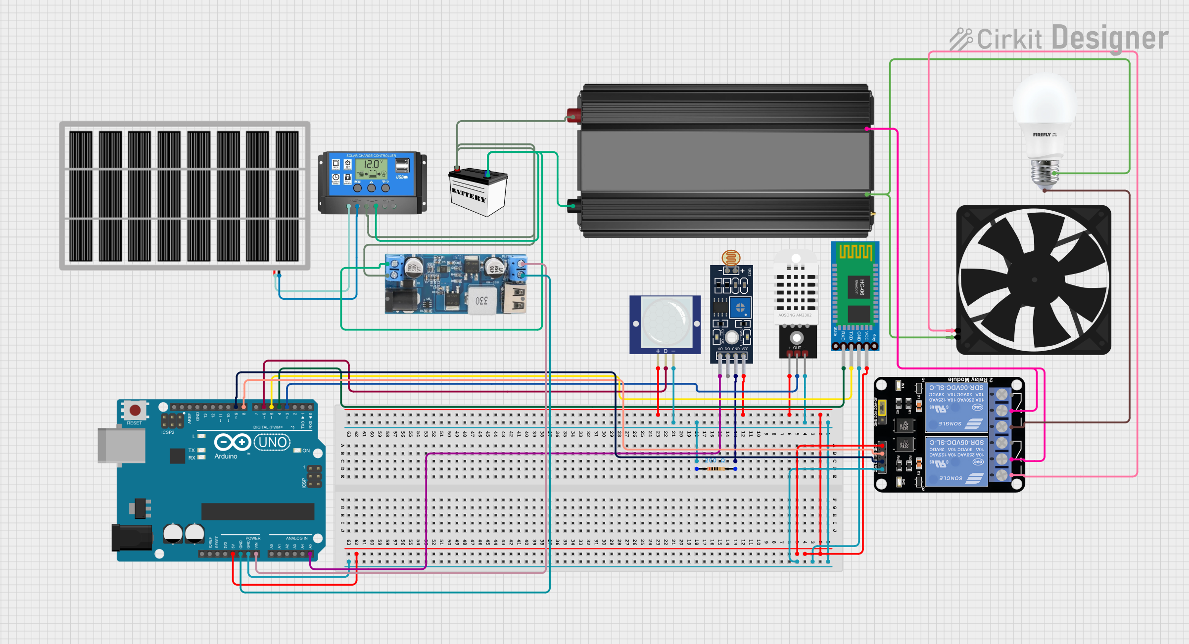
This is a smart control system utilizing an Arduino UNO to interface with Bluetooth communication, light, temperature, humidity, and motion sensors, and to control a relay module for a bulb and a fan. It features a solar-powered charging circuit for energy management and a power inverter to supply AC power to the bulb.
NFC-Enabled Access Control System with Real-Time Clock and OLED Display

This circuit is designed as an access control system with time-tracking capabilities. It uses an NFC/RFID reader for authentication, a real-time clock for time-stamping events, and an OLED display for user interface, all controlled by a T8_S3 microcontroller. A relay module actuates a magnetic lock, and a button switch provides additional user input, with a switching power supply delivering the necessary voltages.
Voice-Activated Home Automation System with Arduino and ESP8266
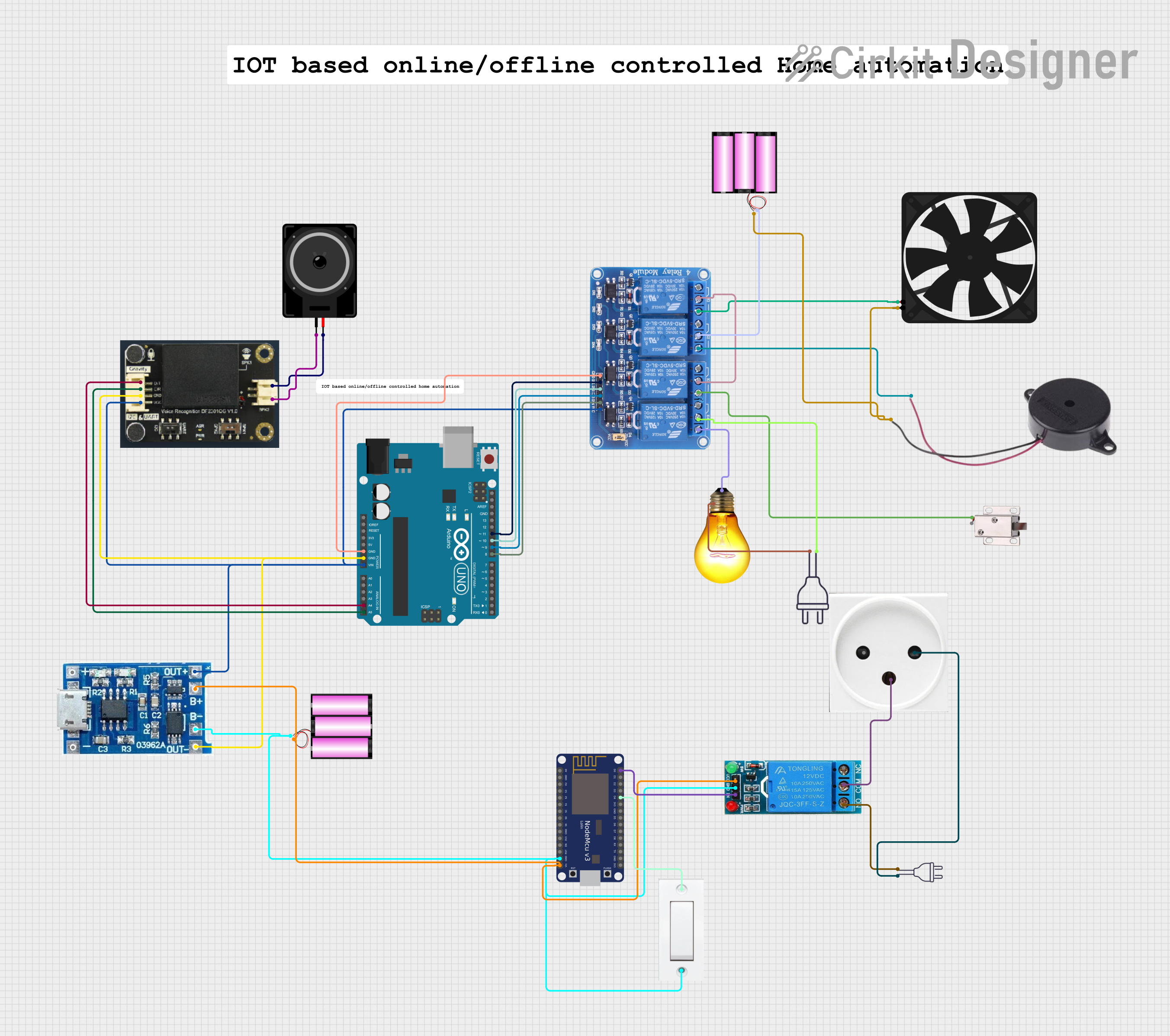
This is a voice-activated control system powered by solar energy with battery backup. It uses an Arduino UNO to interpret voice commands via a DF Robot Gravity voice recognition module and control a 4-channel relay that switches a fan, buzzer, solenoid lock, and AC bulb. A NodeMCU ESP8266 is included for potential IoT connectivity.
Arduino UNO-Based Smart Home Automation System with Bluetooth and IR Control
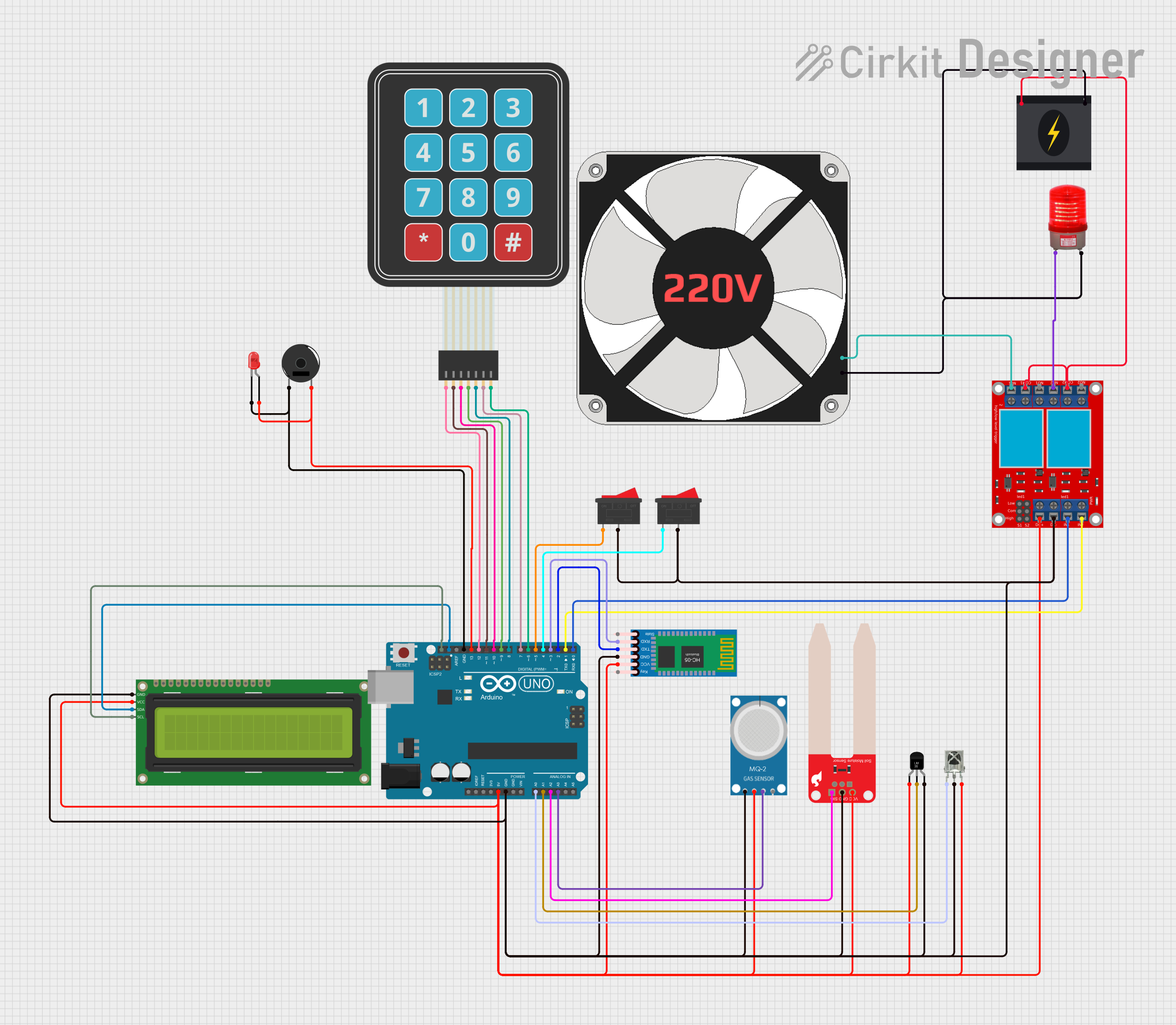
This circuit is a smart home automation system controlled by an Arduino UNO. It integrates various sensors (temperature, soil moisture, smoke, and IR receiver), a Bluetooth module, an LCD display, a keypad, and a relay module to control a fan and a red light. The system can be operated manually, via Bluetooth, or using an IR remote, and it provides feedback through an LCD display and a buzzer.
Explore Projects Built with oui
Arduino UNO-Based Smart Environmental Monitoring and Control System with Bluetooth Connectivity
This is a smart control system utilizing an Arduino UNO to interface with Bluetooth communication, light, temperature, humidity, and motion sensors, and to control a relay module for a bulb and a fan. It features a solar-powered charging circuit for energy management and a power inverter to supply AC power to the bulb.
NFC-Enabled Access Control System with Real-Time Clock and OLED Display
This circuit is designed as an access control system with time-tracking capabilities. It uses an NFC/RFID reader for authentication, a real-time clock for time-stamping events, and an OLED display for user interface, all controlled by a T8_S3 microcontroller. A relay module actuates a magnetic lock, and a button switch provides additional user input, with a switching power supply delivering the necessary voltages.
Voice-Activated Home Automation System with Arduino and ESP8266
This is a voice-activated control system powered by solar energy with battery backup. It uses an Arduino UNO to interpret voice commands via a DF Robot Gravity voice recognition module and control a 4-channel relay that switches a fan, buzzer, solenoid lock, and AC bulb. A NodeMCU ESP8266 is included for potential IoT connectivity.
Arduino UNO-Based Smart Home Automation System with Bluetooth and IR Control
This circuit is a smart home automation system controlled by an Arduino UNO. It integrates various sensors (temperature, soil moisture, smoke, and IR receiver), a Bluetooth module, an LCD display, a keypad, and a relay module to control a fan and a red light. The system can be operated manually, via Bluetooth, or using an IR remote, and it provides feedback through an LCD display and a buzzer.
Technical Specifications
- The "Oui" component is a conceptual device with the following hypothetical specifications:
| Parameter | Value |
|---|---|
| Operating Voltage | 3.3V to 5V |
| Maximum Current | 10mA |
| Power Consumption | < 50mW |
| Logic Level Input | High: 3.3V to 5V, Low: 0V |
| Operating Temperature | -40°C to 85°C |
Pin Configuration and Descriptions
| Pin Number | Pin Name | Description |
|---|---|---|
| 1 | VCC | Power supply input (3.3V to 5V) |
| 2 | GND | Ground connection |
| 3 | IN | Input signal (logic level) |
| 4 | OUT | Output signal (logic level, mirrors IN) |
Usage Instructions
To use the "Oui" component in a circuit:
- Connect the VCC pin to a 3.3V or 5V power source.
- Connect the GND pin to the ground of your circuit.
- Provide a logic-level signal (0V or 3.3V/5V) to the IN pin.
- The OUT pin will output the same logic level as the IN pin, effectively acting as a buffer.
Important Considerations and Best Practices:
- Ensure the operating voltage does not exceed 5V to avoid damaging the component.
- Use a current-limiting resistor if connecting the IN pin to a high-current source.
- Keep the component within the specified operating temperature range for optimal performance.
Arduino UNO Example Code: Below is an example of how to use the "Oui" component with an Arduino UNO:
// Define the input and output pins for the "Oui" component
const int inputPin = 2;  // Connect to the IN pin of the "Oui" component
const int outputPin = 3; // Connect to the OUT pin of the "Oui" component

void setup() {
  pinMode(inputPin, INPUT);  // Set the input pin as an input
  pinMode(outputPin, OUTPUT); // Set the output pin as an output
}

void loop() {
  // Read the state of the input pin
  int inputState = digitalRead(inputPin);

  // Output the same state to the output pin
  digitalWrite(outputPin, inputState);

  // Add a small delay to stabilize the signal
  delay(10);
}
Troubleshooting and FAQs
Common Issues:
- No output signal on the OUT pin:
- Ensure the VCC and GND pins are properly connected.
- Verify that the IN pin is receiving a valid logic-level signal.
- Component overheating:
- Check that the operating voltage does not exceed 5V.
- Ensure the current through the component is within the specified range.
- No output signal on the OUT pin:
FAQs:
- Can the "Oui" component handle analog signals?
- No, the "Oui" component is designed for digital logic signals only.
- What happens if the input signal is floating?
- A floating input may cause unpredictable behavior. Use a pull-up or pull-down resistor to stabilize the input signal.
- Is the "Oui" component compatible with 3.3V systems?
- Yes, the component operates within a voltage range of 3.3V to 5V.
- Can the "Oui" component handle analog signals?
This concludes the documentation for the "Oui" component. While it is a conceptual device, the principles outlined here can be applied to real-world electronic components with similar functionality.