Cirkit Designer Logo
Cirkit Designer
Your all-in-one circuit design IDE
Home / 
Component Documentation

How to Use JOYELEC_relè_Contattore automatico CA domestico 220V / 230V 50 / 60Hz: Examples, Pinouts, and Specs

Image of JOYELEC_relè_Contattore automatico CA domestico 220V / 230V 50 / 60Hz
Cirkit Designer LogoDesign with JOYELEC_relè_Contattore automatico CA domestico 220V / 230V 50 / 60Hz in Cirkit Designer

Introduction

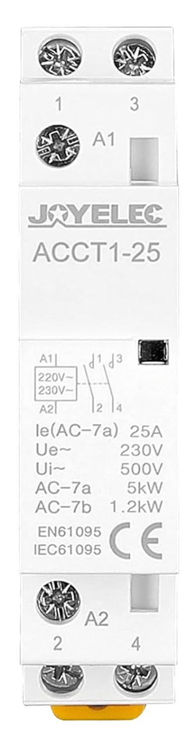
The JOYELEC_relè_Contattore automatico CA domestico 220V / 230V 50 / 60Hz (Manufacturer Part ID: ACCT1) is a domestic AC relay contactor designed for reliable and efficient control of electrical devices. Operating at 220V/230V with a frequency of 50/60Hz, this component is ideal for automating the switching of household appliances, lighting systems, and other electrical loads.

Explore Projects Built with JOYELEC_relè_Contattore automatico CA domestico 220V / 230V 50 / 60Hz

Use Cirkit Designer to design, explore, and prototype these projects online. Some projects support real-time simulation. Click "Open Project" to start designing instantly!
Electromechanical Pump Control Circuit with Emergency Stop
Image of Pelton.: A project utilizing JOYELEC_relè_Contattore automatico CA domestico 220V / 230V 50 / 60Hz in a practical application
This circuit is designed to control a pump using a contactor that is manually operated by a switch and can be overridden by an emergency stop. The contactor enables power from an AC power outlet to the pump, and the emergency stop can interrupt the power circuit for safety purposes.
Cirkit Designer LogoOpen Project in Cirkit Designer
Wi-Fi Enabled Motion-Activated Lighting System with Radar Sensor
Image of CAPSTONE: A project utilizing JOYELEC_relè_Contattore automatico CA domestico 220V / 230V 50 / 60Hz in a practical application
This circuit is designed to control an AC LED bulb using a 220V power source, with an infrared motion sensor and an MMWave radar sensor providing input signals. The two-channel relay is used to switch the LED bulb on and off based on the sensor inputs, while the ESP8266 microcontroller is likely programmed to process the sensor data and control the relay. A converter is included to interface between the sensors, microcontroller, and the relay, ensuring proper voltage levels.
Cirkit Designer LogoOpen Project in Cirkit Designer
Industrial Power Distribution and Safety Control System
Image of Control Diagram: A project utilizing JOYELEC_relè_Contattore automatico CA domestico 220V / 230V 50 / 60Hz in a practical application
This circuit is designed for power distribution and safety control in an industrial setting. It features a main isolator and circuit breaker for power management, multiple PSUs for 5V, 12V, and 24V outputs, and a safety relay system that interfaces with E-stop buttons and a start switch to control a main contactor, ensuring safe operation and emergency power cut-off capabilities.
Cirkit Designer LogoOpen Project in Cirkit Designer
Arduino UNO Controlled Relay System with HC-05 Bluetooth Interface
Image of Heisan: A project utilizing JOYELEC_relè_Contattore automatico CA domestico 220V / 230V 50 / 60Hz in a practical application
This circuit is designed to wirelessly control power to a 220V fan, a 120V outlet, and a 220VAC red light using an Arduino UNO and HC-05 Bluetooth module. The Arduino toggles three 5V relay modules to switch the high-voltage devices, with the potential for remote operation via Bluetooth. The provided code suggests that the control logic for the relays and Bluetooth communication is yet to be developed.
Cirkit Designer LogoOpen Project in Cirkit Designer

Explore Projects Built with JOYELEC_relè_Contattore automatico CA domestico 220V / 230V 50 / 60Hz

Use Cirkit Designer to design, explore, and prototype these projects online. Some projects support real-time simulation. Click "Open Project" to start designing instantly!
Image of Pelton.: A project utilizing JOYELEC_relè_Contattore automatico CA domestico 220V / 230V 50 / 60Hz in a practical application
Electromechanical Pump Control Circuit with Emergency Stop
This circuit is designed to control a pump using a contactor that is manually operated by a switch and can be overridden by an emergency stop. The contactor enables power from an AC power outlet to the pump, and the emergency stop can interrupt the power circuit for safety purposes.
Cirkit Designer LogoOpen Project in Cirkit Designer
Image of CAPSTONE: A project utilizing JOYELEC_relè_Contattore automatico CA domestico 220V / 230V 50 / 60Hz in a practical application
Wi-Fi Enabled Motion-Activated Lighting System with Radar Sensor
This circuit is designed to control an AC LED bulb using a 220V power source, with an infrared motion sensor and an MMWave radar sensor providing input signals. The two-channel relay is used to switch the LED bulb on and off based on the sensor inputs, while the ESP8266 microcontroller is likely programmed to process the sensor data and control the relay. A converter is included to interface between the sensors, microcontroller, and the relay, ensuring proper voltage levels.
Cirkit Designer LogoOpen Project in Cirkit Designer
Image of Control Diagram: A project utilizing JOYELEC_relè_Contattore automatico CA domestico 220V / 230V 50 / 60Hz in a practical application
Industrial Power Distribution and Safety Control System
This circuit is designed for power distribution and safety control in an industrial setting. It features a main isolator and circuit breaker for power management, multiple PSUs for 5V, 12V, and 24V outputs, and a safety relay system that interfaces with E-stop buttons and a start switch to control a main contactor, ensuring safe operation and emergency power cut-off capabilities.
Cirkit Designer LogoOpen Project in Cirkit Designer
Image of Heisan: A project utilizing JOYELEC_relè_Contattore automatico CA domestico 220V / 230V 50 / 60Hz in a practical application
Arduino UNO Controlled Relay System with HC-05 Bluetooth Interface
This circuit is designed to wirelessly control power to a 220V fan, a 120V outlet, and a 220VAC red light using an Arduino UNO and HC-05 Bluetooth module. The Arduino toggles three 5V relay modules to switch the high-voltage devices, with the potential for remote operation via Bluetooth. The provided code suggests that the control logic for the relays and Bluetooth communication is yet to be developed.
Cirkit Designer LogoOpen Project in Cirkit Designer

Common Applications and Use Cases

  • Home Automation: Automating the control of lights, fans, and other appliances.
  • Industrial Control: Managing small-scale machinery or equipment.
  • Energy Management: Switching loads to optimize energy consumption.
  • Safety Systems: Isolating circuits during faults or overloads.

Technical Specifications

The following table outlines the key technical details of the JOYELEC AC relay contactor:

Parameter Specification
Operating Voltage 220V / 230V AC
Frequency 50 / 60 Hz
Rated Current 16A
Contact Configuration SPST (Single Pole Single Throw)
Coil Power Consumption ≤ 2W
Insulation Resistance ≥ 100MΩ
Operating Temperature -10°C to +55°C
Dimensions 86mm x 36mm x 65mm
Weight 150g

Pin Configuration and Descriptions

The relay contactor has the following pin configuration:

Pin Number Label Description
1 L (Line) Connect to the live AC input (220V/230V).
2 N (Neutral) Connect to the neutral AC input.
3 NO (Normally Open) Output terminal for the load; closed when relay is active.
4 COM (Common) Common terminal for the load circuit.

Usage Instructions

How to Use the Component in a Circuit

  1. Power Connection: Connect the live (L) and neutral (N) terminals to the 220V/230V AC power supply.
  2. Load Connection:
    • Connect one terminal of the load to the COM pin.
    • Connect the other terminal of the load to the NO pin.
  3. Control Signal: Use an external control circuit (e.g., a microcontroller or a manual switch) to activate the relay coil.

Important Considerations and Best Practices

  • Voltage Compatibility: Ensure the input voltage matches the rated 220V/230V AC.
  • Current Rating: Do not exceed the rated current of 16A to avoid damage.
  • Proper Insulation: Maintain proper insulation between live and neutral connections to prevent short circuits.
  • Mounting: Securely mount the relay in a well-ventilated area to avoid overheating.
  • Safety Precautions: Always disconnect the power supply before wiring or servicing the relay.

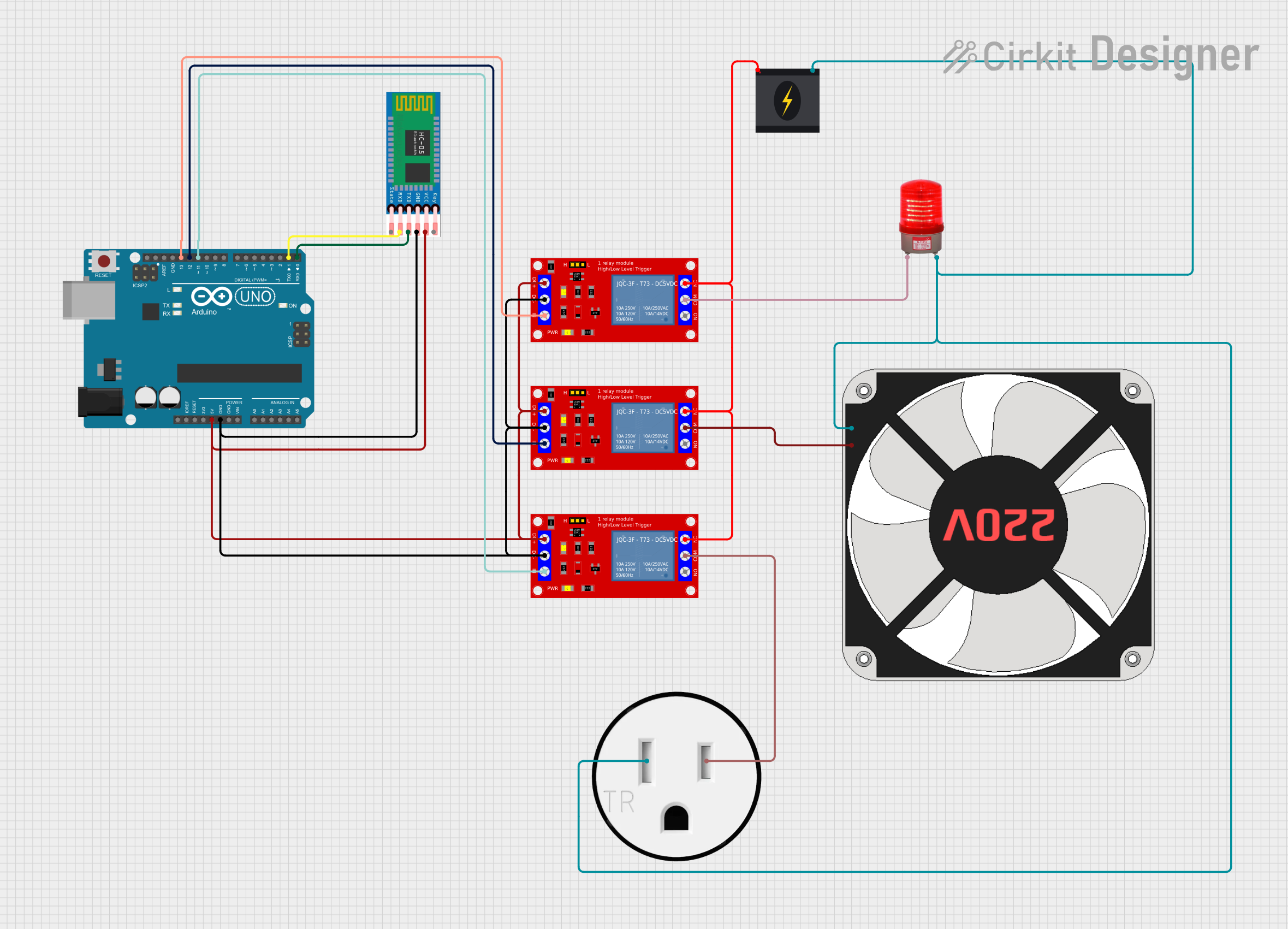
Example: Connecting to an Arduino UNO

The JOYELEC relay can be controlled using an Arduino UNO. Below is an example circuit and code to toggle the relay:

Circuit Setup

  1. Connect the relay's control input to a digital pin on the Arduino (e.g., pin 7).
  2. Use a transistor (e.g., 2N2222) and a flyback diode (e.g., 1N4007) to drive the relay safely.
  3. Connect the Arduino's GND to the relay's GND.

Arduino Code

// Define the pin connected to the relay
const int relayPin = 7;

void setup() {
  pinMode(relayPin, OUTPUT); // Set the relay pin as an output
  digitalWrite(relayPin, LOW); // Ensure the relay is off initially
}

void loop() {
  digitalWrite(relayPin, HIGH); // Turn the relay on
  delay(5000); // Keep it on for 5 seconds
  digitalWrite(relayPin, LOW); // Turn the relay off
  delay(5000); // Keep it off for 5 seconds
}

Note: Use a proper relay driver circuit to protect the Arduino from high currents.

Troubleshooting and FAQs

Common Issues and Solutions

  1. Relay Not Activating:

    • Cause: Insufficient control voltage or incorrect wiring.
    • Solution: Verify the control voltage and ensure proper connections.
  2. Overheating:

    • Cause: Exceeding the rated current or poor ventilation.
    • Solution: Reduce the load current and ensure adequate airflow around the relay.
  3. Buzzing Noise:

    • Cause: Fluctuating input voltage or loose connections.
    • Solution: Stabilize the input voltage and tighten all connections.
  4. Load Not Switching:

    • Cause: Faulty relay contacts or incorrect load wiring.
    • Solution: Check the load wiring and test the relay contacts for continuity.

FAQs

  • Q: Can this relay be used with DC loads?

    • A: No, this relay is designed for AC loads only. For DC loads, use a DC-specific relay.
  • Q: Is the relay suitable for outdoor use?

    • A: No, the relay is not weatherproof. Use it in indoor environments only.
  • Q: Can I control the relay directly from an Arduino pin?

    • A: No, the Arduino pin cannot supply enough current. Use a transistor or relay driver circuit.
  • Q: What is the maximum load power this relay can handle?

    • A: The relay can handle up to 16A at 230V AC, which equals 3680W.

By following this documentation, users can effectively integrate the JOYELEC AC relay contactor into their projects for reliable and efficient operation.