How to Use Vietduino Uno USB-B: Examples, Pinouts, and Specs
Introduction
The Vietduino Uno USB-B is a microcontroller board based on the ATmega328P, designed and manufactured by Makerlabvn. It is fully compatible with Arduino Uno, making it an excellent choice for hobbyists, educators, and professionals for rapid prototyping and educational purposes. The board is equipped with a USB-B connector for programming and serial communication, which differentiates it from boards using other USB interfaces.
Explore Projects Built with Vietduino Uno USB-B
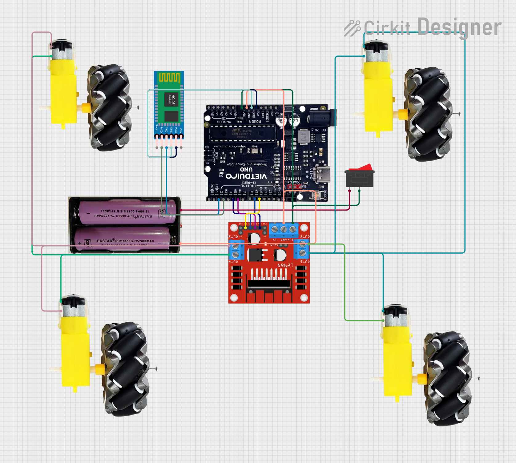
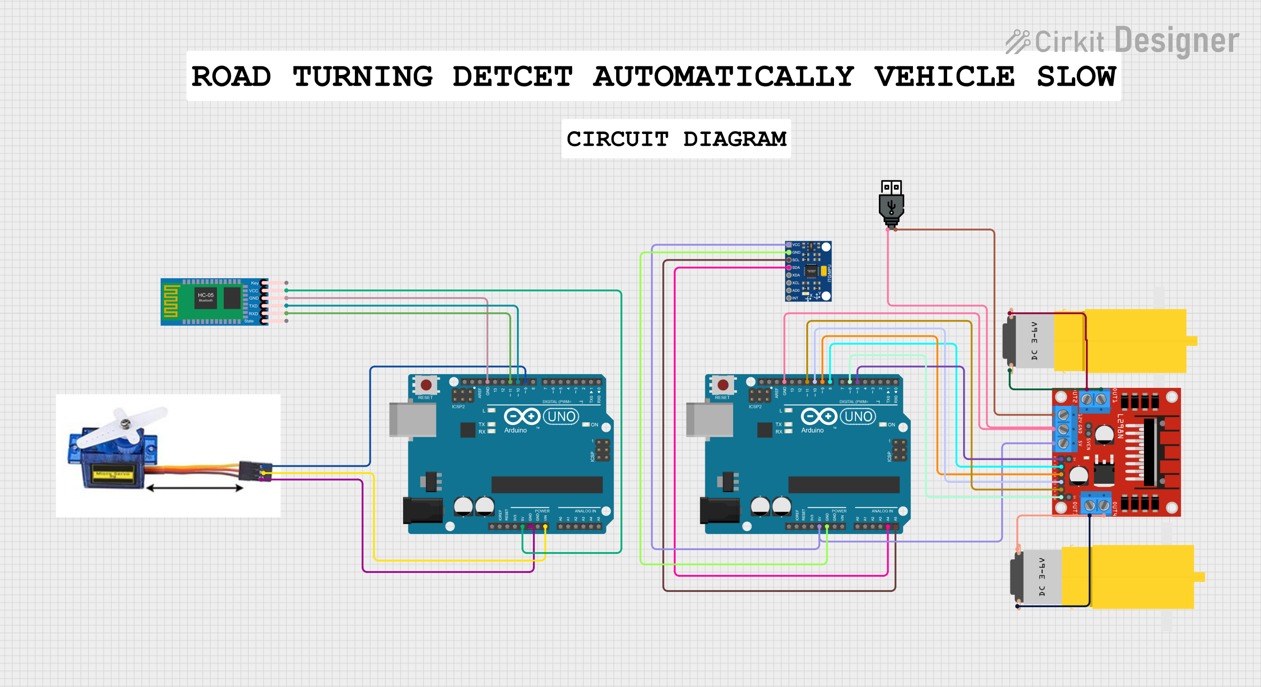
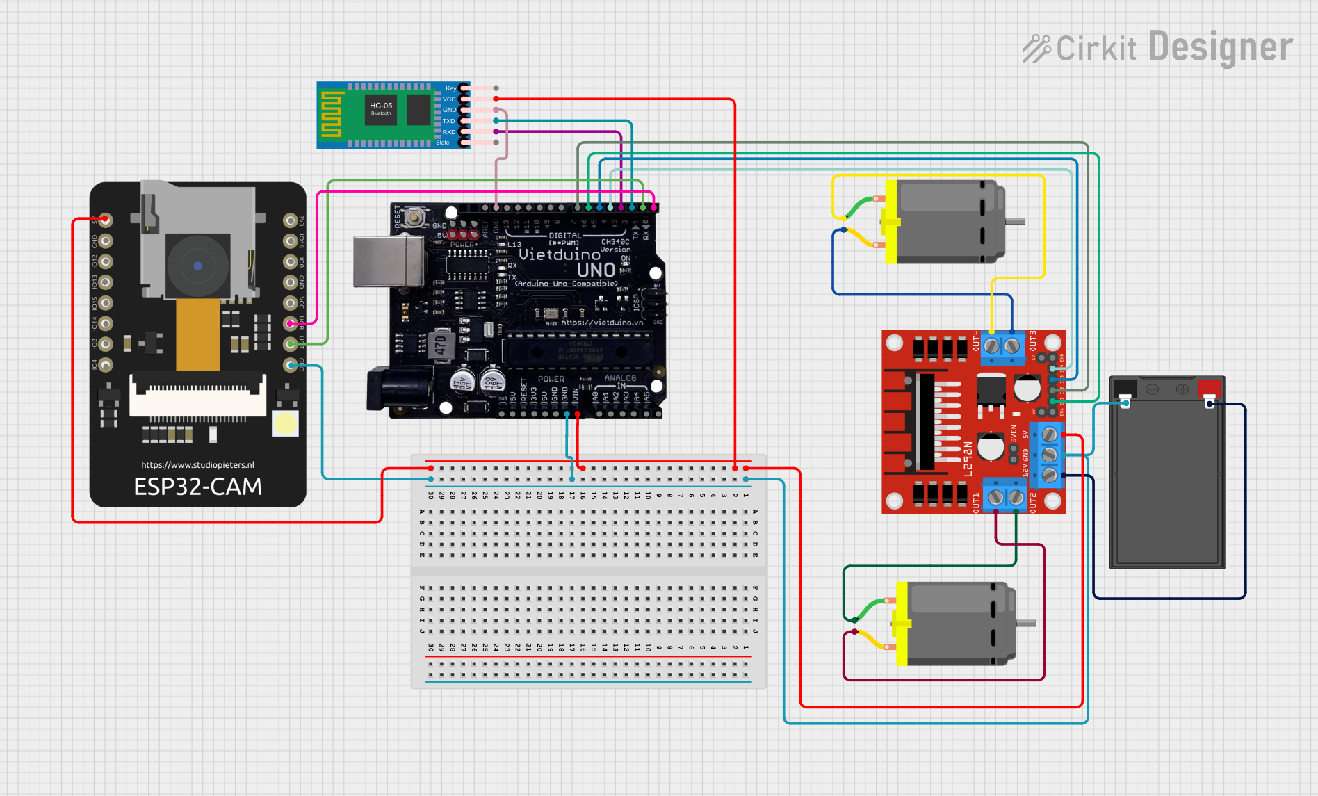
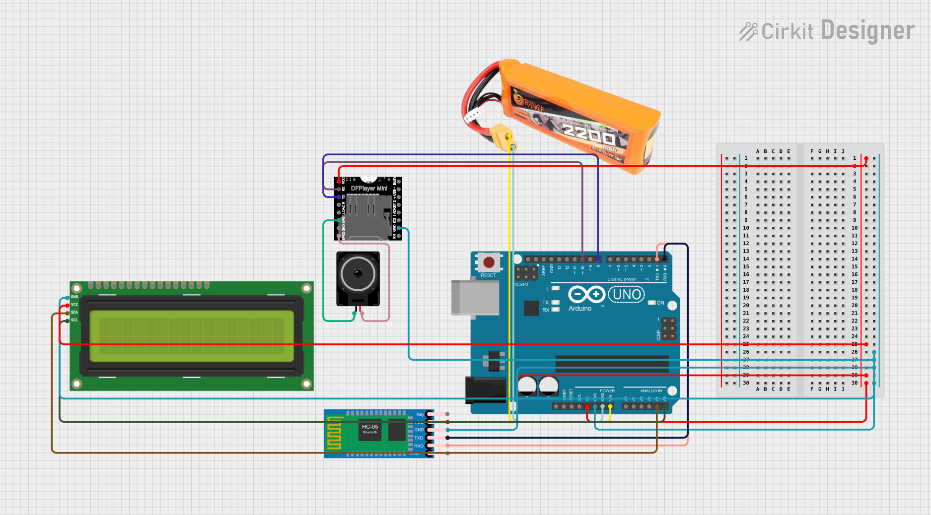
Explore Projects Built with Vietduino Uno USB-B
Common Applications and Use Cases
- Educational projects and learning the basics of electronics and programming
- DIY electronics projects
- Prototyping IoT (Internet of Things) devices
- Robotics and control systems
- Interactive artworks
Technical Specifications
Key Technical Details
- Microcontroller: ATmega328P
- Operating Voltage: 5V
- Input Voltage (recommended): 7-12V
- Input Voltage (limit): 6-20V
- Digital I/O Pins: 14 (of which 6 provide PWM output)
- Analog Input Pins: 6
- DC Current per I/O Pin: 20 mA
- DC Current for 3.3V Pin: 50 mA
- Flash Memory: 32 KB (ATmega328P) of which 0.5 KB used by bootloader
- SRAM: 2 KB (ATmega328P)
- EEPROM: 1 KB (ATmega328P)
- Clock Speed: 16 MHz
- LED_BUILTIN: Pin 13
Pin Configuration and Descriptions
| Pin Number | Function | Description |
|---|---|---|
| 1 | RESET | Used to reset the microcontroller |
| 2-13 | Digital I/O | Digital pins for input/output. PWM available on 3,5,6,9,10,11 |
| 14-19 | Analog Input | A0-A5 analog input pins |
| 20 | GND | Ground |
| 21 | AREF | Analog reference voltage for the ADC |
| 22 | 3V3 | 3.3V supply generated by the onboard regulator |
| 23 | D13/LED_BUILTIN | Built-in LED connected to digital pin 13 |
| 24 | 5V | Regulated 5V supply voltage |
| 25 | GND | Ground |
| 26 | Vin | Input voltage to the board |
| 27-28 | I2C (TWI) | SDA and SCL pins for I2C communication |
| 29-30 | RX/TX | Serial communication pins |
| 31 | RESET | Reset pin, also accessible externally |
| 32 | GND | Ground |
| 33 | USB-B | USB interface for programming and communication |
Usage Instructions
How to Use the Component in a Circuit
Powering the Board:
- Connect a 7-12V power supply to the Vin and GND pins, or plug a USB-B cable connected to a computer or USB power source into the USB port.
Programming the Board:
- Install the Arduino IDE from the official Arduino website.
- Connect the Vietduino Uno USB-B to your computer using a USB-B cable.
- Select "Arduino/Genuino Uno" from the Tools > Board menu in the Arduino IDE.
- Choose the correct serial port from Tools > Port.
- Write or open your sketch (program) and click the "Upload" button to program the board.
Using Digital and Analog Pins:
- Connect sensors, actuators, or other components to the digital and analog pins as required by your project.
- Ensure that the components are compatible with the operating voltage and current limitations of the pins.
Important Considerations and Best Practices
- Always disconnect the board from the power source before making or altering connections.
- Do not exceed the recommended voltage and current ratings to avoid damaging the board.
- Use a current-limiting resistor when connecting LEDs to digital pins.
- Utilize the onboard LED connected to pin 13 for testing and debugging.
- When using PWM pins, ensure that the connected devices are compatible with PWM signals.
Troubleshooting and FAQs
Common Issues Users Might Face
Board not recognized by the computer:
- Check the USB cable and connections.
- Ensure that the correct drivers are installed.
- Try a different USB port or computer.
Sketch not uploading:
- Verify that the correct board and port are selected in the Arduino IDE.
- Check for errors in the code that may prevent compilation.
- Ensure that the bootloader is functioning correctly.
Unexpected behavior in circuits:
- Double-check wiring and connections.
- Ensure power supply stability and adequacy.
- Verify that the code corresponds to the intended functionality.
Solutions and Tips for Troubleshooting
- Use the Arduino IDE's Serial Monitor to debug and monitor serial communication.
- Implement "blink" or "echo" tests to confirm basic functionality.
- Consult the Makerlabvn community forums or Arduino forums for support.
Example Code for Arduino UNO
// Blink the onboard LED connected to pin 13

void setup() {
  pinMode(LED_BUILTIN, OUTPUT); // Initialize the LED pin as an output
}

void loop() {
  digitalWrite(LED_BUILTIN, HIGH); // Turn the LED on
  delay(1000);                     // Wait for a second
  digitalWrite(LED_BUILTIN, LOW);  // Turn the LED off
  delay(1000);                     // Wait for a second
}
This example code will blink the onboard LED of the Vietduino Uno USB-B. It is a simple test to ensure that the board is functioning correctly. Remember to select the correct board and port in the Arduino IDE before uploading the sketch.