How to Use Raspberry Pi Camera Module 3: Examples, Pinouts, and Specs
Introduction
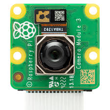
The Raspberry Pi Camera Module 3 is a high-quality camera module designed for seamless integration with Raspberry Pi boards. It features improved image quality, autofocus functionality, and support for various resolutions and frame rates. This makes it an excellent choice for projects involving photography, video recording, and computer vision applications. Its compact size and versatility allow it to be used in a wide range of projects, from home security systems to AI-powered image recognition.
Explore Projects Built with Raspberry Pi Camera Module 3
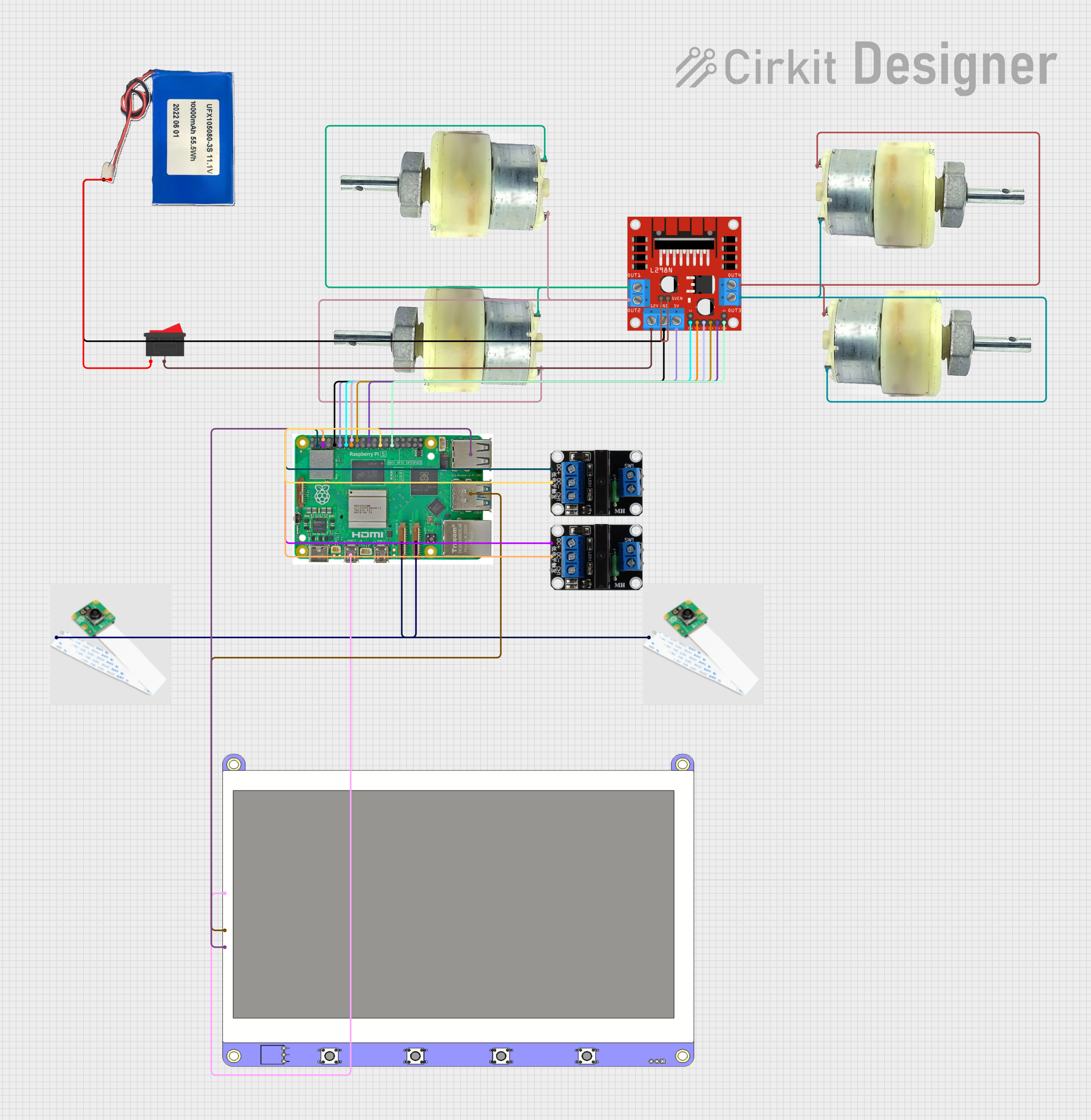
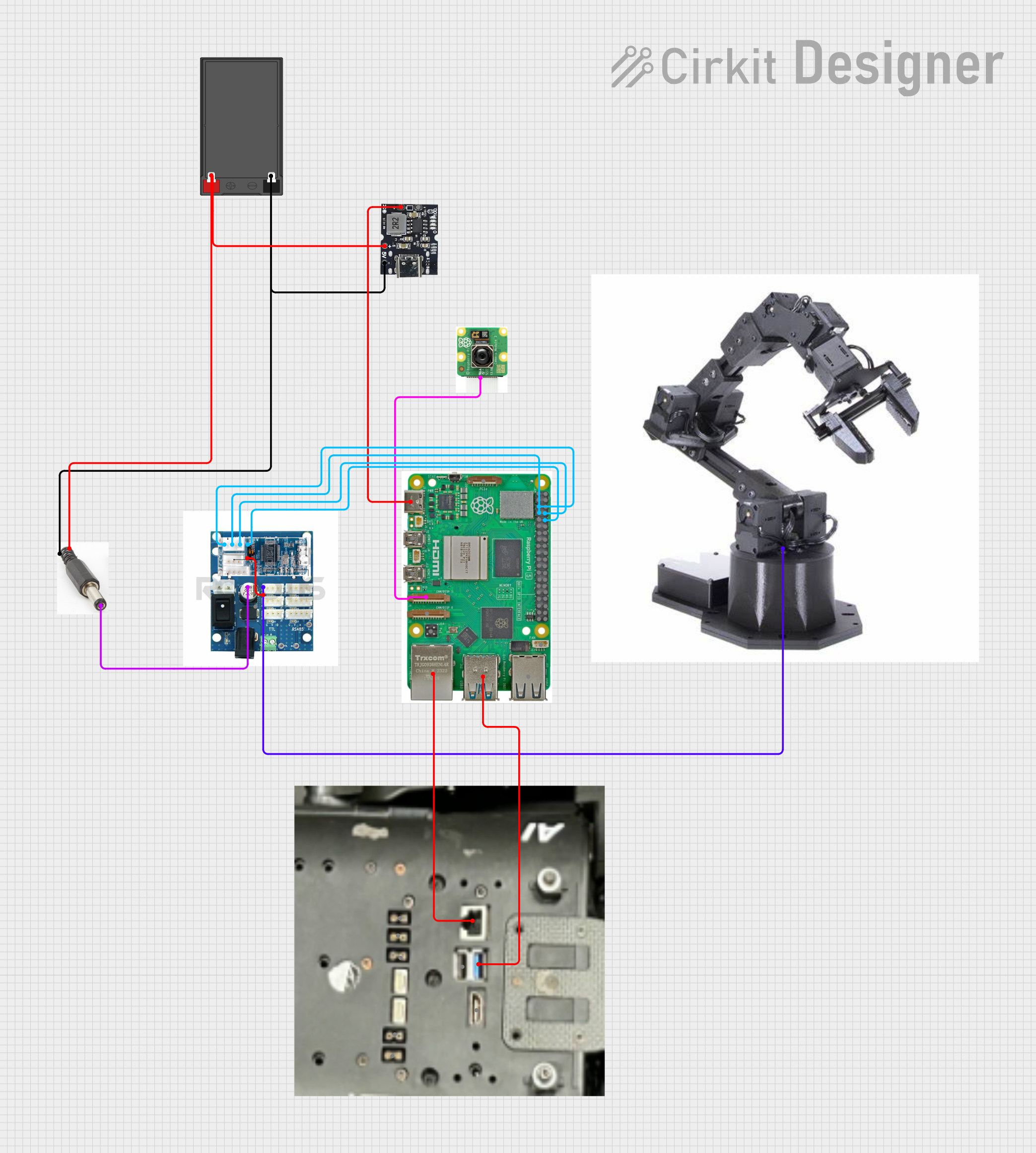
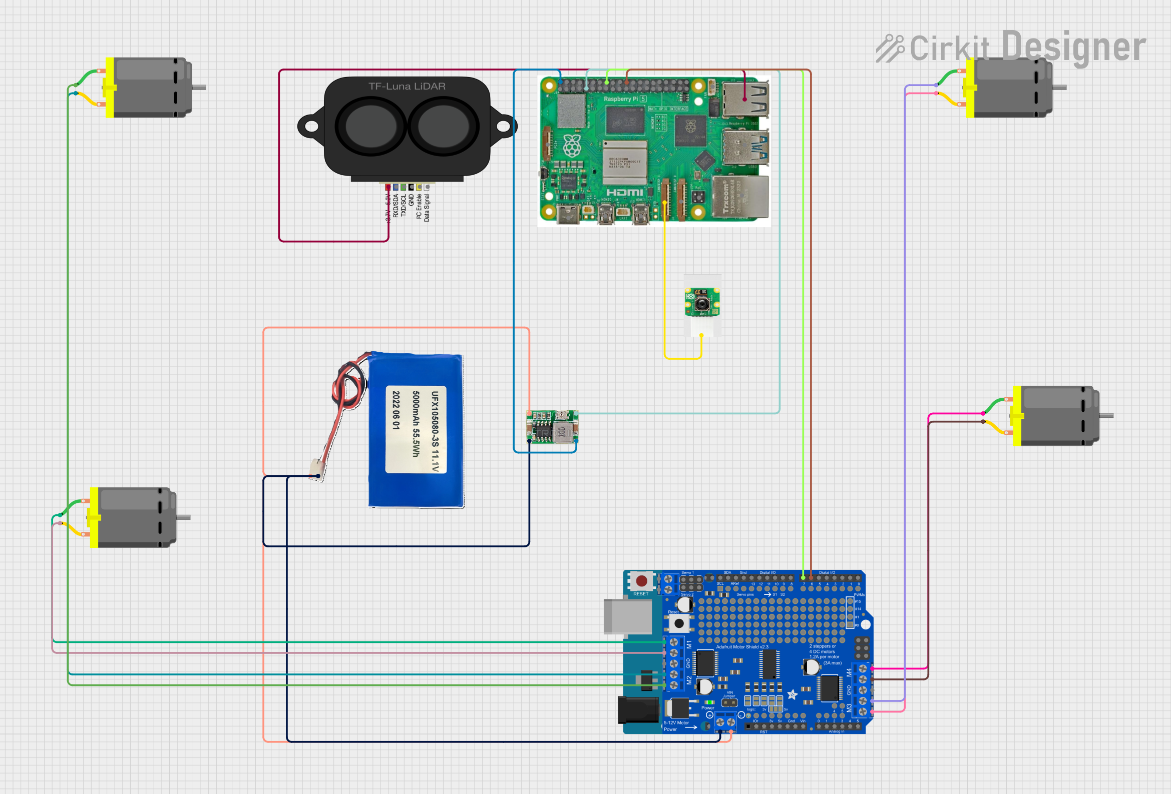
Explore Projects Built with Raspberry Pi Camera Module 3
Common Applications
- Photography and video recording
- Computer vision and machine learning projects
- Home automation and security systems
- Time-lapse photography
- Robotics and object tracking
Technical Specifications
The Raspberry Pi Camera Module 3 is available in multiple variants, including standard and wide-angle lenses, as well as visible light and infrared (NoIR) versions. Below are the key technical details:
Key Specifications
- Sensor: Sony IMX708
- Resolution: 12 megapixels
- Autofocus: Yes
- Field of View (FoV):
- Standard: 66° horizontal
- Wide-angle: 102° horizontal
- Video Modes:
- 1080p at 50 fps
- 720p at 100 fps
- 640 × 480 (VGA) at 120 fps
- Interface: MIPI CSI-2
- Power Supply: 3.3V (via Raspberry Pi)
- Dimensions: 25 × 24 × 11.5 mm (excluding cable)
- Weight: 3g (approx.)
Pin Configuration
The Raspberry Pi Camera Module 3 connects to the Raspberry Pi board via the CSI (Camera Serial Interface) connector. Below is the pin configuration for the CSI interface:
| Pin Number | Pin Name | Description |
|---|---|---|
| 1 | GND | Ground |
| 2 | 3.3V Power | Power supply for the camera module |
| 3 | I2C SDA | I2C data line for camera communication |
| 4 | I2C SCL | I2C clock line for camera communication |
| 5 | CSI Data Lane 0+ | Positive differential data signal |
| 6 | CSI Data Lane 0- | Negative differential data signal |
| 7 | CSI Clock Lane+ | Positive differential clock signal |
| 8 | CSI Clock Lane- | Negative differential clock signal |
| 9 | CSI Data Lane 1+ | Positive differential data signal |
| 10 | CSI Data Lane 1- | Negative differential data signal |
Usage Instructions
Connecting the Camera Module
- Power Off the Raspberry Pi: Always power off the Raspberry Pi before connecting or disconnecting the camera module to avoid damage.
- Locate the CSI Port: The CSI port is typically located near the HDMI port on the Raspberry Pi board.
- Insert the Ribbon Cable:
- Open the CSI port's plastic clip by gently pulling it upward.
- Insert the ribbon cable with the metal contacts facing the HDMI port.
- Push the plastic clip back down to secure the cable.
- Power On the Raspberry Pi: Once the camera is securely connected, power on the Raspberry Pi.
Enabling the Camera
- Open a terminal on the Raspberry Pi.
- Run the following command to open the Raspberry Pi configuration tool:
sudo raspi-config - Navigate to Interface Options > Camera and enable the camera.
- Reboot the Raspberry Pi to apply the changes:
sudo reboot
Capturing Images and Videos
The Raspberry Pi Camera Module 3 can be controlled using the libcamera tools. Below are examples of capturing images and videos:
Capturing an Image
libcamera-still -o image.jpg
Captures an image and saves it as 'image.jpg' in the current directory.
Recording a Video
libcamera-vid -o video.h264 -t 10000
Records a 10-second video and saves it as 'video.h264'.
The '-t' option specifies the duration in milliseconds.
Using the Camera with Python
The picamera2 library allows you to control the camera module in Python. Below is an example:
from picamera2 import Picamera2
import time
Initialize the camera
picam2 = Picamera2()
Configure the camera for preview
picam2.configure(picam2.preview_configuration())
Start the camera
picam2.start() print("Camera is running...")
Capture an image after 5 seconds
time.sleep(5) picam2.capture_file("image.jpg") print("Image captured and saved as 'image.jpg'.")
Stop the camera
picam2.stop() print("Camera stopped.")
Best Practices
- Ensure the ribbon cable is securely connected to avoid intermittent issues.
- Use a stable power supply to prevent the camera from malfunctioning.
- Avoid touching the camera lens to prevent smudges or scratches.
- Use a compatible Raspberry Pi OS version for optimal performance.
Troubleshooting and FAQs
Common Issues and Solutions
1. Camera Not Detected
- Cause: The camera module is not enabled in the Raspberry Pi configuration.
- Solution: Run
sudo raspi-configand enable the camera under Interface Options. Reboot the Raspberry Pi.
2. Poor Image Quality
- Cause: Dirty or scratched lens.
- Solution: Clean the lens gently with a microfiber cloth. Avoid using abrasive materials.
3. Autofocus Not Working
- Cause: Insufficient lighting or subject too close.
- Solution: Ensure adequate lighting and maintain a minimum distance of 10 cm from the subject.
4. "libcamera" Command Not Found
- Cause: Missing or outdated software.
- Solution: Update the Raspberry Pi OS and install the required packages:
sudo apt update
sudo apt install -y libcamera-apps
FAQs
Q: Can I use the Camera Module 3 with older Raspberry Pi models?
A: Yes, the Camera Module 3 is compatible with most Raspberry Pi models that have a CSI port. However, performance may vary depending on the model.
Q: Does the Camera Module 3 support night vision?
A: The NoIR version of the Camera Module 3 is designed for low-light and night vision applications.
Q: Can I use multiple Camera Modules with a single Raspberry Pi?
A: Yes, but you will need a multi-camera adapter board to connect multiple cameras.
Q: What is the maximum resolution supported?
A: The Camera Module 3 supports a maximum resolution of 12 megapixels for still images.
By following this documentation, you can effectively integrate and utilize the Raspberry Pi Camera Module 3 in your projects.