Cirkit Designer Logo
Cirkit Designer
Your all-in-one circuit design IDE
Home / 
Component Documentation

How to Use stepper driver: Examples, Pinouts, and Specs

Image of stepper driver
Cirkit Designer LogoDesign with stepper driver in Cirkit Designer

Introduction

The TB6600 stepper driver is a widely-used electronic component designed to drive stepper motors, which are commonly used in CNC machines, 3D printers, and other precision motion control applications. The TB6600 provides an easy and efficient way to control stepper motors with high precision and reliability.

Explore Projects Built with stepper driver

Use Cirkit Designer to design, explore, and prototype these projects online. Some projects support real-time simulation. Click "Open Project" to start designing instantly!
Arduino-Controlled Stepper and DC Motor with Relay Switching
Image of Conveyor Belt & Capping Motor: A project utilizing stepper driver in a practical application
This circuit controls a Nema 17 stepper motor using a DRV8825 driver module, with an Arduino UNO microcontroller dictating the step and direction. Additionally, the circuit can switch a DC motor on and off using a relay module controlled by the Arduino. The power supply provides the necessary voltage for the relay and the motor driver, which in turn powers the stepper motor, while the Arduino's firmware defines the motor's stepping behavior and the relay's switching to control the DC motor.
Cirkit Designer LogoOpen Project in Cirkit Designer
Stepper Motor Control System with TB6600 Driver and DKC-1A Controller
Image of Copy of Copy of PLC-Based Step Motor Speed and Direction Control System: A project utilizing stepper driver in a practical application
This circuit controls a bipolar stepper motor using a tb6600 micro stepping motor driver and a DKC-1A stepper motor controller. The system is powered by a 24VDC power supply and includes a relay module for additional control functionalities.
Cirkit Designer LogoOpen Project in Cirkit Designer
Arduino-Controlled Stepper Motor with LCD Interface and Rotary Encoder
Image of AC Servo Motor: A project utilizing stepper driver in a practical application
This circuit is designed to control a bipolar stepper motor using an Arduino Mega 2560 microcontroller and a STEPPERONLINE DM542T driver. The Arduino interfaces with a 20x4 LCD display over I2C for user feedback, a membrane matrix keypad for user input, and a rotary encoder for precise control inputs. The power supply provides the necessary voltage and current to drive the stepper motor through the DM542T driver.
Cirkit Designer LogoOpen Project in Cirkit Designer
Arduino UNO Controlled Bipolar Stepper Motor with Keypad Interface
Image of Attenuator with LCD: A project utilizing stepper driver in a practical application
This circuit controls a bipolar stepper motor using an Arduino UNO and an A4988/DRV8825 stepper motor driver. The Arduino provides control signals to the driver, which in turn powers and controls the stepper motor, allowing for precise movement control.
Cirkit Designer LogoOpen Project in Cirkit Designer

Explore Projects Built with stepper driver

Use Cirkit Designer to design, explore, and prototype these projects online. Some projects support real-time simulation. Click "Open Project" to start designing instantly!
Image of Conveyor Belt & Capping Motor: A project utilizing stepper driver in a practical application
Arduino-Controlled Stepper and DC Motor with Relay Switching
This circuit controls a Nema 17 stepper motor using a DRV8825 driver module, with an Arduino UNO microcontroller dictating the step and direction. Additionally, the circuit can switch a DC motor on and off using a relay module controlled by the Arduino. The power supply provides the necessary voltage for the relay and the motor driver, which in turn powers the stepper motor, while the Arduino's firmware defines the motor's stepping behavior and the relay's switching to control the DC motor.
Cirkit Designer LogoOpen Project in Cirkit Designer
Image of Copy of Copy of PLC-Based Step Motor Speed and Direction Control System: A project utilizing stepper driver in a practical application
Stepper Motor Control System with TB6600 Driver and DKC-1A Controller
This circuit controls a bipolar stepper motor using a tb6600 micro stepping motor driver and a DKC-1A stepper motor controller. The system is powered by a 24VDC power supply and includes a relay module for additional control functionalities.
Cirkit Designer LogoOpen Project in Cirkit Designer
Image of AC Servo Motor: A project utilizing stepper driver in a practical application
Arduino-Controlled Stepper Motor with LCD Interface and Rotary Encoder
This circuit is designed to control a bipolar stepper motor using an Arduino Mega 2560 microcontroller and a STEPPERONLINE DM542T driver. The Arduino interfaces with a 20x4 LCD display over I2C for user feedback, a membrane matrix keypad for user input, and a rotary encoder for precise control inputs. The power supply provides the necessary voltage and current to drive the stepper motor through the DM542T driver.
Cirkit Designer LogoOpen Project in Cirkit Designer
Image of Attenuator with LCD: A project utilizing stepper driver in a practical application
Arduino UNO Controlled Bipolar Stepper Motor with Keypad Interface
This circuit controls a bipolar stepper motor using an Arduino UNO and an A4988/DRV8825 stepper motor driver. The Arduino provides control signals to the driver, which in turn powers and controls the stepper motor, allowing for precise movement control.
Cirkit Designer LogoOpen Project in Cirkit Designer

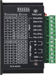
Technical Specifications

Key Technical Details

  • Supply Voltage: 9V to 42V DC
  • Output Current: Adjustable from 0.5A to 4.0A (peak)
  • Input Signal Voltage: 3.3V to 24V (high level)
  • Microstepping: Full, 1/2, 1/4, 1/8, 1/16, 1/32 selectable
  • Operating Temperature: -10°C to 45°C
  • Dimensions: 96mm x 71mm x 39mm

Pin Configuration and Descriptions

Pin Number Pin Name Description
1 ENA+ Enable signal positive
2 ENA- Enable signal negative
3 DIR+ Direction signal positive
4 DIR- Direction signal negative
5 PUL+ Pulse signal positive
6 PUL- Pulse signal negative
7 A+ Motor coil A positive
8 A- Motor coil A negative
9 B+ Motor coil B positive
10 B- Motor coil B negative
11 VCC Power supply positive
12 GND Power supply ground

Usage Instructions

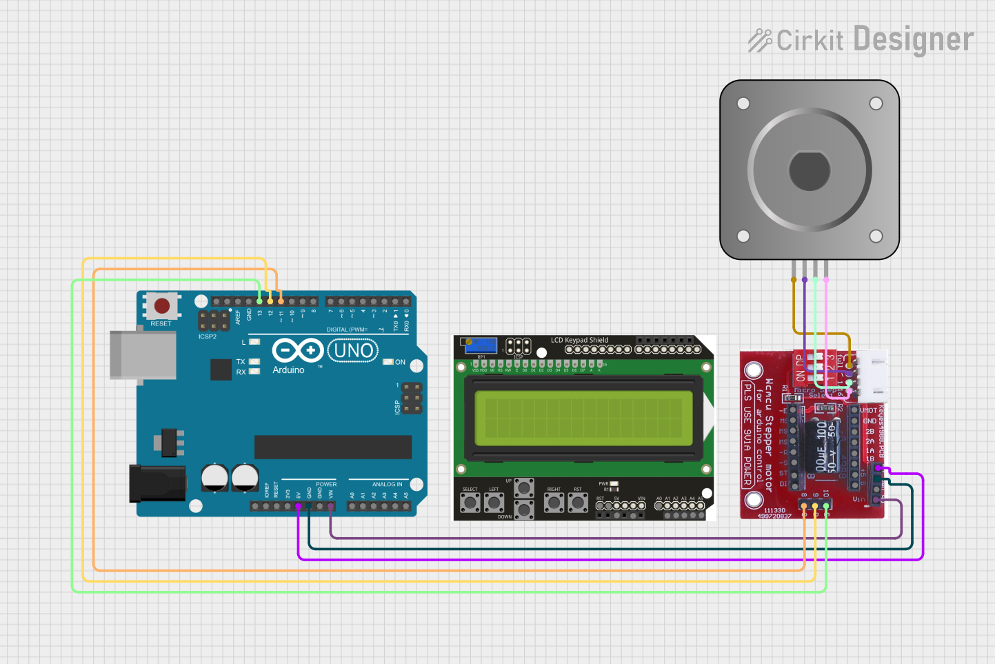
Connecting the TB6600 to a Stepper Motor

  1. Power Supply: Connect a DC power supply to the VCC and GND pins, ensuring the voltage is within the specified range.
  2. Motor Connection: Connect the motor coils to the A+ and A-, and B+ and B- terminals.
  3. Control Signals: Connect the ENA+, DIR+, and PUL+ to the respective control signals, and ENA-, DIR-, and PUL- to the ground or negative control signals.

Important Considerations and Best Practices

  • Always ensure the power supply is turned off before making any connections.
  • Set the current limit according to the motor's specifications to prevent damage.
  • Use appropriate heat sinks if operating at high currents for extended periods.
  • Microstepping settings should be configured based on the application's precision requirements.

Example Code for Arduino UNO

// Define the stepper motor connections and steps per revolution
#define dirPin 2
#define stepPin 3
#define stepsPerRevolution 200

void setup() {
  // Set the motor control pins as outputs
  pinMode(dirPin, OUTPUT);
  pinMode(stepPin, OUTPUT);
}

void loop() {
  // Set the spinning direction clockwise
  digitalWrite(dirPin, HIGH);

  // Spin the motor one revolution slowly
  for (int i = 0; i < stepsPerRevolution; i++) {
    // These four lines result in 1 step:
    digitalWrite(stepPin, HIGH);
    delayMicroseconds(2000);
    digitalWrite(stepPin, LOW);
    delayMicroseconds(2000);
  }

  delay(1000); // Wait a second

  // Set the spinning direction counterclockwise
  digitalWrite(dirPin, LOW);

  // Spin the motor one revolution quickly
  for (int i = 0; i < stepsPerRevolution; i++) {
    // These four lines result in 1 step:
    digitalWrite(stepPin, HIGH);
    delayMicroseconds(1000); // This delay controls the speed
    digitalWrite(stepPin, LOW);
    delayMicroseconds(1000);
  }

  delay(1000); // Wait a second
}

Troubleshooting and FAQs

Common Issues

  • Motor not moving: Check power supply, connections, and ensure the enable pin is set correctly.
  • Motor stalling or skipping steps: Adjust current limit, check for mechanical obstructions, or reduce speed.
  • Overheating: Ensure proper current settings and use heat sinks if necessary.

FAQs

Q: Can I use the TB6600 with a 5V logic controller? A: Yes, the TB6600 is compatible with 3.3V to 24V logic levels.

Q: How do I set the current limit on the TB6600? A: The current limit is set using the onboard dip switches according to the motor's specifications.

Q: What is the maximum stepping frequency for the TB6600? A: The TB6600 can handle a maximum pulse frequency of up to 200kHz.

For further assistance, consult the manufacturer's datasheet and technical support resources.