The TP4056 is a lithium-ion battery charger IC manufactured by Electrokit. It is designed to provide a constant current/constant voltage (CC/CV) charging profile, making it ideal for charging single-cell lithium-ion batteries. The IC integrates several safety features, including over-voltage protection, under-voltage lockout, and thermal regulation, ensuring safe and efficient charging.
Explore Projects Built with TP4056
Use Cirkit Designer to design, explore, and prototype these projects online. Some projects support real-time simulation. Click "Open Project" to start designing instantly!
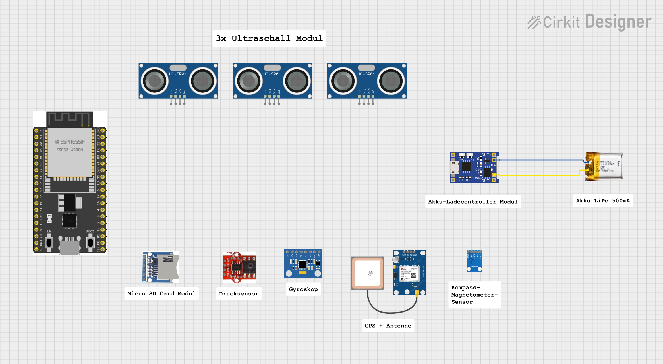
This circuit consists of a TP4056 module connected to a 3.7V LiPo battery, providing a charging interface for the battery. The TP4056 manages the charging process by connecting its B+ and B- pins to the battery's positive and ground terminals, respectively.
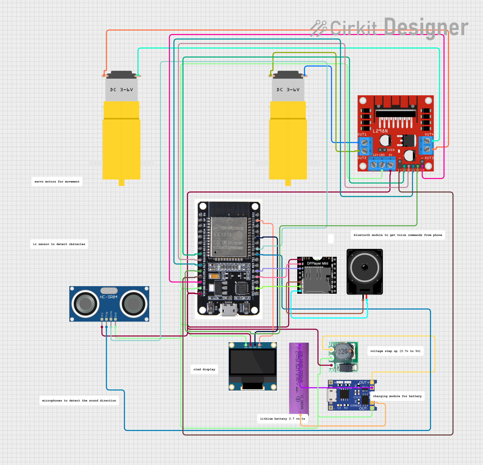
This circuit is a battery-powered system featuring an ESP32 microcontroller that controls an OLED display, a motor driver for two hobby motors, an ultrasonic sensor for distance measurement, and a DFPlayer Mini for audio output through a loudspeaker. The TP4056 module manages battery charging, and a step-up boost converter provides a stable 5V supply to the components.
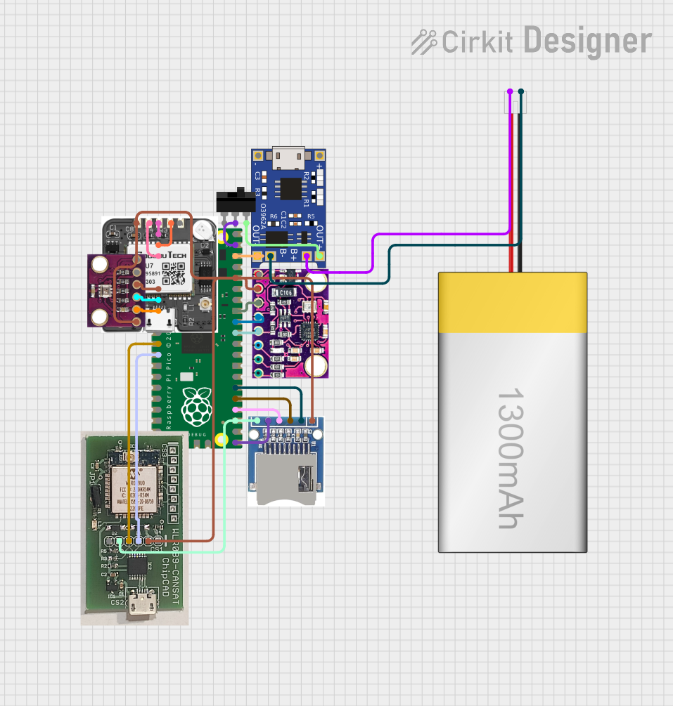
This circuit is a data acquisition and communication system powered by a LiPoly battery and managed by a Raspberry Pi Pico. It includes sensors (BMP280, MPU9250) for environmental data, a GPS module for location tracking, an SD card for data storage, and a WLR089-CanSAT for wireless communication. The TP4056 module handles battery charging, and a toggle switch controls power distribution.
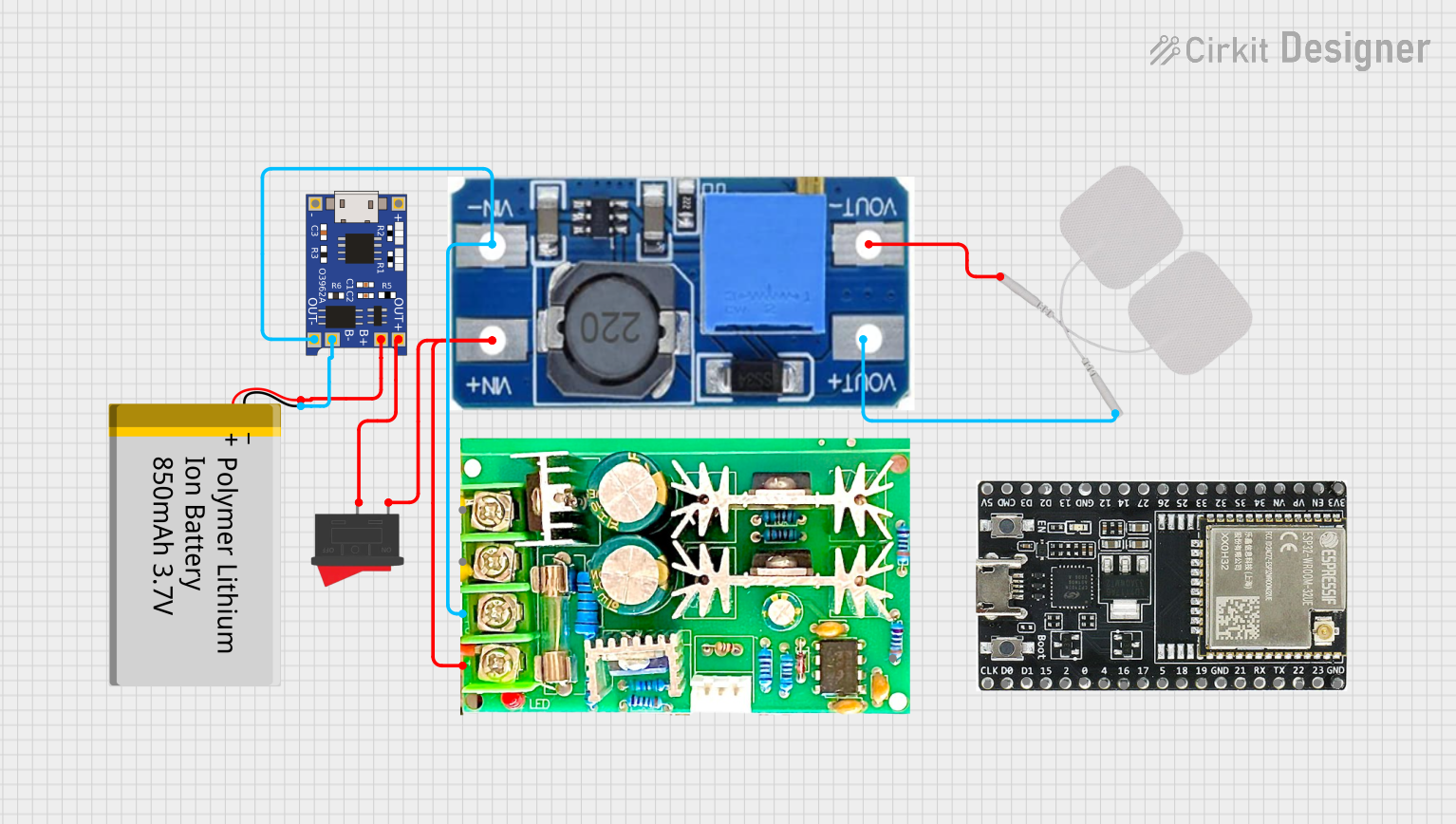
This circuit is designed to control the speed of a motor using a PWM motor speed controller powered by a Lithium-Ion battery. The TP4056 module manages battery charging, while a step-up boost converter regulates the voltage supplied to the motor and an Elektro Pad. A rocker switch is included to control the power flow to the motor speed controller.
The TP4056 is typically available in an 8-pin SOP package. Below is the pin configuration and description:
Pin Number
Pin Name
Description
1
TEMP
Temperature sense input. Connect to an NTC thermistor for battery temperature monitoring.
2
PROG
Programs the charging current. Connect a resistor to ground to set the current.
3
GND
Ground connection.
4
VCC
Input supply voltage (4.0V to 8.0V).
5
BAT
Battery connection pin. Connect directly to the positive terminal of the battery.
6
STDBY
Status indicator pin. Low when charging is complete.
7
CHRG
Status indicator pin. Low when charging is in progress.
8
CE
Chip enable. Active low to enable the IC.
Usage Instructions
The TP4056 is straightforward to use in a circuit. Below are the steps and considerations for proper usage:
How to Use the TP4056 in a Circuit
Power Supply: Connect a DC power source (4.0V to 8.0V) to the VCC pin. Ensure the power source can supply sufficient current for the charging process.
Battery Connection: Connect the positive terminal of the lithium-ion battery to the BAT pin and the negative terminal to GND.
Programming Charging Current: Use a resistor (RPROG) between the PROG pin and GND to set the charging current. The charging current (ICHG) can be calculated using the formula:
[
I_{CHG} = \frac{1200}{R_{PROG}}
]
For example, a 1.2kΩ resistor sets the charging current to 1A.
Status Indicators: Connect LEDs to the CHRG and STDBY pins (with appropriate current-limiting resistors) to monitor the charging status:
CHRG pin: Low when charging is in progress.
STDBY pin: Low when charging is complete.
Temperature Monitoring: Optionally, connect an NTC thermistor to the TEMP pin for battery temperature monitoring. If unused, connect TEMP to GND.
Important Considerations and Best Practices
Thermal Management: Ensure proper heat dissipation, especially when charging at high currents. Use a PCB with adequate thermal vias and copper planes.
Battery Protection: Use a protection circuit module (PCM) with the battery to prevent over-discharge and over-current conditions.
Input Voltage: Avoid exceeding the maximum input voltage of 8.0V to prevent damage to the IC.
Current Limiting: Select the RPROG resistor carefully to avoid overcharging the battery.
Example: Using TP4056 with Arduino UNO
The TP4056 can be used in conjunction with an Arduino UNO to monitor the charging status. Below is an example code snippet:
// TP4056 Status Monitoring with Arduino UNO
// Connect CHRG pin to Arduino pin 2 and STDBY pin to Arduino pin 3

const int chrgPin = 2;  // CHRG pin of TP4056 connected to Arduino pin 2
const int stdbyPin = 3; // STDBY pin of TP4056 connected to Arduino pin 3

void setup() {
  pinMode(chrgPin, INPUT);  // Set CHRG pin as input
  pinMode(stdbyPin, INPUT); // Set STDBY pin as input
  Serial.begin(9600);       // Initialize serial communication
}

void loop() {
  int chrgStatus = digitalRead(chrgPin);  // Read CHRG pin status
  int stdbyStatus = digitalRead(stdbyPin); // Read STDBY pin status

  if (chrgStatus == LOW) {
    Serial.println("Charging in progress...");
  } else if (stdbyStatus == LOW) {
    Serial.println("Charging complete.");
  } else {
    Serial.println("No battery connected or standby mode.");
  }

  delay(1000); // Wait for 1 second before checking again
}
Troubleshooting and FAQs
Common Issues and Solutions
Problem: The battery is not charging.
Solution: Check the input voltage at the VCC pin. Ensure it is within the 4.0V to 8.0V range.
Solution: Verify the RPROG resistor value to ensure the charging current is set correctly.
Solution: Ensure the battery is properly connected to the BAT and GND pins.
Problem: The IC overheats during operation.
Solution: Reduce the charging current by increasing the RPROG resistor value.
Solution: Improve PCB thermal management by adding copper planes or heat sinks.
Problem: Status LEDs are not functioning.
Solution: Check the connections and current-limiting resistors for the LEDs.
Solution: Verify the CHRG and STDBY pin voltages during operation.
FAQs
Can the TP4056 charge multiple batteries in series?
No, the TP4056 is designed for single-cell lithium-ion batteries only.
What happens if the input voltage exceeds 8.0V?
Exceeding 8.0V can damage the IC. Always use a regulated power supply within the specified range.
Can I use the TP4056 without the TEMP pin?
Yes, if temperature monitoring is not required, connect the TEMP pin to GND.
How do I adjust the charging current?
Use the formula ( I_{CHG} = \frac{1200}{R_{PROG}} ) to calculate the required RPROG resistor value.
This concludes the TP4056 documentation. For further assistance, refer to the manufacturer's datasheet or contact Electrokit support.


 Open Project in Cirkit Designer