
How to Use ESP32-S3: Examples, Pinouts, and Specs
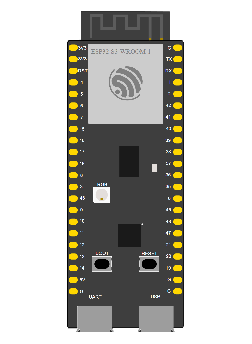
 Design with ESP32-S3 in Cirkit Designer
Introduction
The ESP32-S3, manufactured by Automata (Part ID: ESP32), is a high-performance microcontroller designed for Internet of Things (IoT) applications. It combines integrated Wi-Fi and Bluetooth capabilities with a dual-core processor, making it ideal for projects requiring wireless communication and advanced processing power. The ESP32-S3 also features a wide range of GPIO pins and peripheral support, enabling developers to create complex and versatile applications.
Explore Projects Built with ESP32-S3
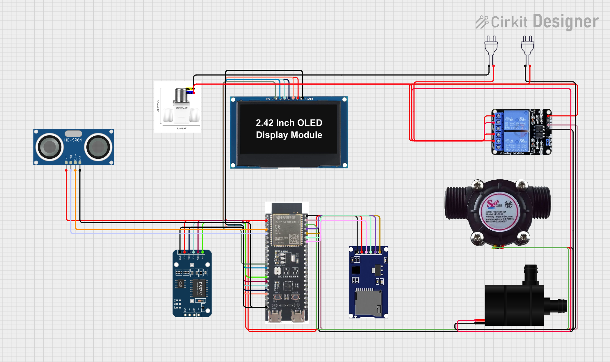 Open Project in Cirkit Designer
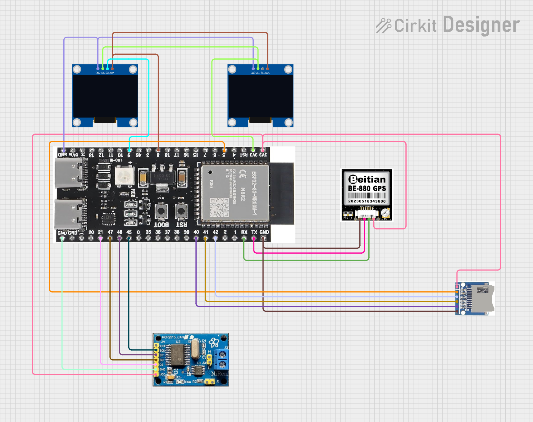 Open Project in Cirkit Designer
 Open Project in Cirkit Designer
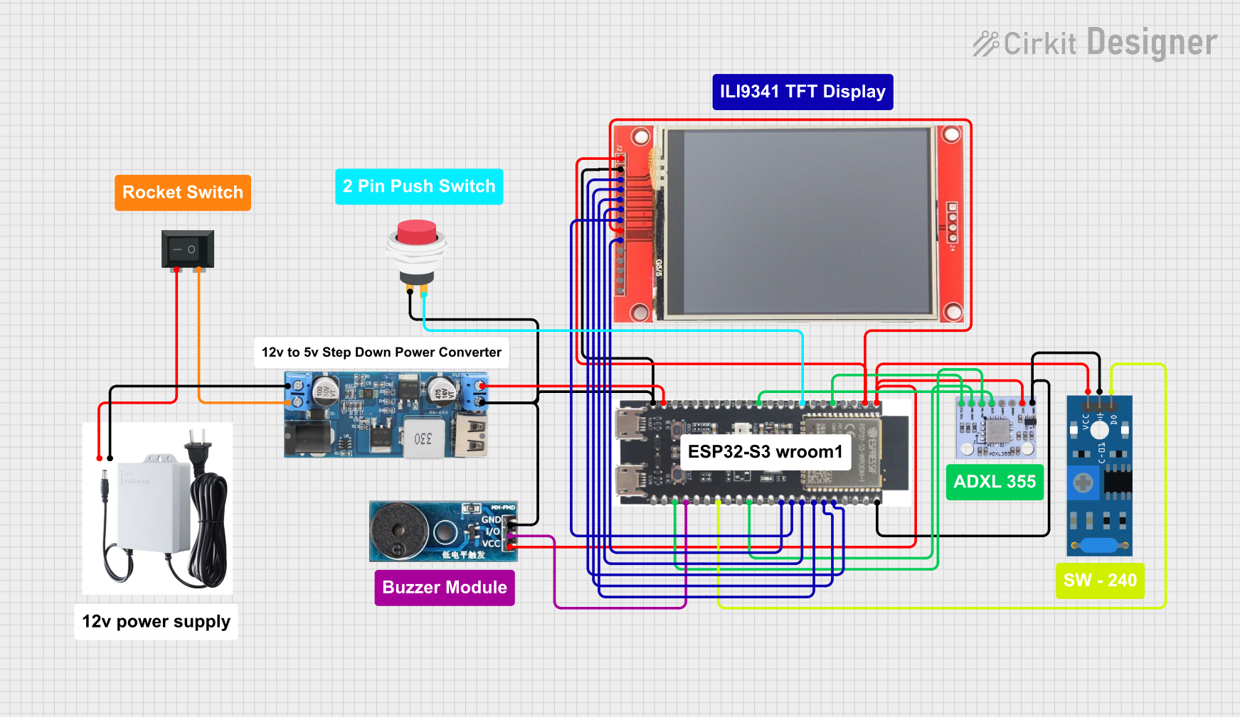 Open Project in Cirkit Designer
Explore Projects Built with ESP32-S3
Open Project in Cirkit DesignerOpen Project in Cirkit DesignerOpen Project in Cirkit DesignerOpen Project in Cirkit DesignerCommon Applications and Use Cases
- Smart home devices (e.g., smart lights, thermostats)
- Wearable technology
- Industrial IoT systems
- Wireless sensor networks
- Robotics and automation
- Audio streaming and voice recognition systems
Technical Specifications
The following table outlines the key technical details of the ESP32-S3:
| Parameter | Specification |
|---|---|
| Processor | Dual-core Xtensa® LX7 @ up to 240 MHz |
| Wireless Connectivity | Wi-Fi 802.11 b/g/n (2.4 GHz), Bluetooth 5.0 LE |
| Flash Memory | Up to 16 MB |
| SRAM | 512 KB |
| GPIO Pins | 45 (configurable for various functions) |
| Operating Voltage | 3.0V to 3.6V |
| Power Consumption | Ultra-low power in deep sleep mode (~10 µA) |
| Interfaces | SPI, I2C, I2S, UART, ADC, DAC, PWM, CAN, Ethernet |
| ADC Resolution | 12-bit |
| DAC Resolution | 8-bit |
| Temperature Range | -40°C to +85°C |
| Package | QFN48 |
Pin Configuration and Descriptions
The ESP32-S3 has a total of 45 GPIO pins, which can be configured for various functions. Below is a table summarizing the key pins and their descriptions:
| Pin Name | Function | Description |
|---|---|---|
| GPIO0 | Boot Mode Selection | Used for boot mode selection during startup |
| GPIO1 | UART TX | Transmit pin for UART communication |
| GPIO3 | UART RX | Receive pin for UART communication |
| GPIO12-15 | SPI Interface | SPI communication pins (MISO, MOSI, SCLK, CS) |
| GPIO21 | I2C SDA | Data line for I2C communication |
| GPIO22 | I2C SCL | Clock line for I2C communication |
| GPIO25-26 | DAC1, DAC2 | Digital-to-Analog Converter outputs |
| GPIO32-39 | ADC1 Channels | Analog-to-Digital Converter input channels |
| EN | Enable | Chip enable pin (active high) |
| GND | Ground | Ground connection |
| 3V3 | Power Supply | 3.3V power input |
Note: Many GPIO pins are multiplexed and can serve multiple functions. Refer to the official datasheet for detailed pin mapping.
Usage Instructions
How to Use the ESP32-S3 in a Circuit
- Power Supply: Connect the ESP32-S3 to a stable 3.3V power source. Ensure the current supply meets the device's requirements, especially during Wi-Fi or Bluetooth transmission.
- Boot Mode: To upload code, connect GPIO0 to GND and reset the device. After uploading, disconnect GPIO0 from GND and reset again to run the program.
- Peripherals: Use the appropriate pins for peripherals like sensors, actuators, or communication modules. For example:
- Use GPIO21 and GPIO22 for I2C devices.
- Use GPIO12-15 for SPI communication.
- Programming: The ESP32-S3 can be programmed using the Arduino IDE, ESP-IDF, or other compatible environments.
Important Considerations and Best Practices
- Voltage Levels: Ensure all connected peripherals operate at 3.3V logic levels to avoid damaging the ESP32-S3.
- Decoupling Capacitors: Place decoupling capacitors (e.g., 0.1 µF) near the power pins to stabilize the power supply.
- Antenna Placement: For optimal wireless performance, ensure the onboard antenna is not obstructed by metal objects or other components.
- Deep Sleep Mode: Use deep sleep mode to conserve power in battery-operated applications.
Example Code for Arduino UNO
Below is an example of how to use the ESP32-S3 to connect to a Wi-Fi network and print the IP address:
#include <WiFi.h> // Include the Wi-Fi library for ESP32

// Replace with your network credentials
const char* ssid = "Your_SSID";
const char* password = "Your_PASSWORD";

void setup() {
  Serial.begin(115200); // Initialize serial communication
  delay(1000); // Wait for serial monitor to initialize

  Serial.println("Connecting to Wi-Fi...");
  WiFi.begin(ssid, password); // Start Wi-Fi connection

  // Wait until the ESP32 connects to Wi-Fi
  while (WiFi.status() != WL_CONNECTED) {
    delay(500);
    Serial.print(".");
  }

  Serial.println("\nConnected to Wi-Fi!");
  Serial.print("IP Address: ");
  Serial.println(WiFi.localIP()); // Print the assigned IP address
}

void loop() {
  // Add your main code here
}
Note: Replace
Your_SSIDandYour_PASSWORDwith your Wi-Fi network credentials.
Troubleshooting and FAQs
Common Issues and Solutions
ESP32-S3 Not Connecting to Wi-Fi
- Solution: Double-check the SSID and password. Ensure the Wi-Fi network is 2.4 GHz, as the ESP32-S3 does not support 5 GHz networks.
Code Upload Fails
- Solution: Ensure GPIO0 is connected to GND during code upload. Verify the correct COM port and board settings in the Arduino IDE.
Device Keeps Resetting
- Solution: Check the power supply. Insufficient current can cause the ESP32-S3 to reset repeatedly.
Poor Wireless Signal
- Solution: Ensure the onboard antenna is unobstructed and positioned away from metal objects.
FAQs
Q: Can the ESP32-S3 operate on 5V?
- A: No, the ESP32-S3 operates at 3.3V. Connecting 5V directly to its pins may damage the device.
Q: How many devices can the ESP32-S3 connect to via Bluetooth?
- A: The ESP32-S3 supports Bluetooth 5.0 LE, allowing multiple simultaneous connections, depending on the application.
Q: Can I use the ESP32-S3 for audio processing?
- A: Yes, the ESP32-S3 supports I2S for audio input/output and has sufficient processing power for audio applications.
Q: Is the ESP32-S3 compatible with the Arduino IDE?
- A: Yes, the ESP32-S3 can be programmed using the Arduino IDE with the appropriate board package installed.
For further assistance, refer to the official ESP32-S3 datasheet or contact Automata support.