Cirkit Designer Logo
Cirkit Designer
Your all-in-one circuit design IDE
Home / 
Component Documentation

How to Use MPU9250/GY -91: Examples, Pinouts, and Specs

Image of MPU9250/GY -91
Cirkit Designer LogoDesign with MPU9250/GY -91 in Cirkit Designer

Introduction

The MPU9250/GY-91 is a multi-faceted motion tracking device that integrates a 3-axis gyroscope, a 3-axis accelerometer, and a 3-axis compass. This 9-axis sensor is widely used in the field of robotics, wearable devices, and motion-based game controllers, providing precise data for orientation and motion sensing.

Explore Projects Built with MPU9250/GY -91

Use Cirkit Designer to design, explore, and prototype these projects online. Some projects support real-time simulation. Click "Open Project" to start designing instantly!
ESP32-Based Accident Detection and GPS Tracking System with GSM Notifications
Image of hello: A project utilizing MPU9250/GY -91 in a practical application
This circuit features an ESP32 microcontroller interfaced with an MPU6050 accelerometer/gyroscope, a Neo 6M GPS module, and a SIM800L GSM module. The ESP32 communicates with the MPU6050 via I2C (SCL and SDA lines) to detect potential accidents based on acceleration thresholds, with the GPS module providing location data via a serial connection (RX0 and TX0). The SIM800L GSM module is connected to the ESP32 through another serial interface (RX2 and TX2) to send SMS alerts with location information in case of an accident detection.
Cirkit Designer LogoOpen Project in Cirkit Designer
Battery-Powered ESP32 and MPU-6050 Motion Sensor
Image of EN21485954: A project utilizing MPU9250/GY -91 in a practical application
This circuit consists of an ESP32 microcontroller connected to an MPU-6050 accelerometer and gyroscope sensor, powered by a Li-ion battery. The ESP32 communicates with the MPU-6050 via I2C protocol, with the SDA and SCL lines connected to D21 and D22 pins of the ESP32, respectively. The circuit is designed for motion sensing and data acquisition applications.
Cirkit Designer LogoOpen Project in Cirkit Designer
Arduino Nano and MPU-9250 Based 9-DoF Sensor Fusion System
Image of yawtiltroll: A project utilizing MPU9250/GY -91 in a practical application
This circuit interfaces an Arduino Nano with an MPU-9250 sensor to capture and process 9-axis motion data, including accelerometer, gyroscope, and magnetometer readings. The Arduino Nano runs a sketch that initializes the sensor, performs self-tests, calibrates the sensor, and processes the motion data using Madgwick and Mahony filter algorithms for sensor fusion.
Cirkit Designer LogoOpen Project in Cirkit Designer
ESP32-Controlled Multi-MPU6050 and MPU9250 IMU Data Aggregator
Image of gant vr: A project utilizing MPU9250/GY -91 in a practical application
This circuit features an ESP32 microcontroller interfaced with multiple MPU-6050 sensors and a single MPU-9250 sensor through an Adafruit TCA9548A I2C multiplexer, allowing for the reading of multiple inertial measurement units (IMUs) over the same I2C bus. The ESP32 collects and processes acceleration and gyroscopic data from the sensors to calculate angles in the X and Y axes. Power management is handled by a TP4056 charging module and an AMS1117 voltage regulator, which together with two 18650 Li-ion batteries, provide a stable power supply for the microcontroller and sensors.
Cirkit Designer LogoOpen Project in Cirkit Designer

Explore Projects Built with MPU9250/GY -91

Use Cirkit Designer to design, explore, and prototype these projects online. Some projects support real-time simulation. Click "Open Project" to start designing instantly!
Image of hello: A project utilizing MPU9250/GY -91 in a practical application
ESP32-Based Accident Detection and GPS Tracking System with GSM Notifications
This circuit features an ESP32 microcontroller interfaced with an MPU6050 accelerometer/gyroscope, a Neo 6M GPS module, and a SIM800L GSM module. The ESP32 communicates with the MPU6050 via I2C (SCL and SDA lines) to detect potential accidents based on acceleration thresholds, with the GPS module providing location data via a serial connection (RX0 and TX0). The SIM800L GSM module is connected to the ESP32 through another serial interface (RX2 and TX2) to send SMS alerts with location information in case of an accident detection.
Cirkit Designer LogoOpen Project in Cirkit Designer
Image of EN21485954: A project utilizing MPU9250/GY -91 in a practical application
Battery-Powered ESP32 and MPU-6050 Motion Sensor
This circuit consists of an ESP32 microcontroller connected to an MPU-6050 accelerometer and gyroscope sensor, powered by a Li-ion battery. The ESP32 communicates with the MPU-6050 via I2C protocol, with the SDA and SCL lines connected to D21 and D22 pins of the ESP32, respectively. The circuit is designed for motion sensing and data acquisition applications.
Cirkit Designer LogoOpen Project in Cirkit Designer
Image of yawtiltroll: A project utilizing MPU9250/GY -91 in a practical application
Arduino Nano and MPU-9250 Based 9-DoF Sensor Fusion System
This circuit interfaces an Arduino Nano with an MPU-9250 sensor to capture and process 9-axis motion data, including accelerometer, gyroscope, and magnetometer readings. The Arduino Nano runs a sketch that initializes the sensor, performs self-tests, calibrates the sensor, and processes the motion data using Madgwick and Mahony filter algorithms for sensor fusion.
Cirkit Designer LogoOpen Project in Cirkit Designer
Image of gant vr: A project utilizing MPU9250/GY -91 in a practical application
ESP32-Controlled Multi-MPU6050 and MPU9250 IMU Data Aggregator
This circuit features an ESP32 microcontroller interfaced with multiple MPU-6050 sensors and a single MPU-9250 sensor through an Adafruit TCA9548A I2C multiplexer, allowing for the reading of multiple inertial measurement units (IMUs) over the same I2C bus. The ESP32 collects and processes acceleration and gyroscopic data from the sensors to calculate angles in the X and Y axes. Power management is handled by a TP4056 charging module and an AMS1117 voltage regulator, which together with two 18650 Li-ion batteries, provide a stable power supply for the microcontroller and sensors.
Cirkit Designer LogoOpen Project in Cirkit Designer

Common Applications and Use Cases

  • Inertial Measurement Units (IMUs) for robotics
  • Orientation tracking for virtual reality (VR) devices
  • Motion analysis in sports technology
  • Drone stabilization and navigation
  • Smartphone and tablet motion features

Technical Specifications

Key Technical Details

  • Voltage: 2.4V - 3.6V
  • Current: 10μA in low-power accelerometer only mode
  • Gyroscope Range: ±250, ±500, ±1000, ±2000°/sec
  • Accelerometer Range: ±2g, ±4g, ±8g, ±16g
  • Magnetometer Range (Compass): ±4800μT
  • Communication: I2C/SPI

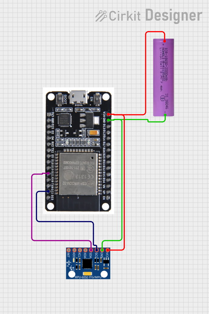
Pin Configuration and Descriptions

Pin Number Pin Name Description
1 VCC Power supply (2.4V - 3.6V)
2 GND Ground
3 SCL/SCLK I2C clock/SPI clock
4 SDA/SDI I2C data/SPI data input
5 AD0/SDO I2C address selection/SPI data output
6 NCS SPI chip select (active low)
7 INT Interrupt output
8 FSYNC Frame synchronization digital input (optional)

Usage Instructions

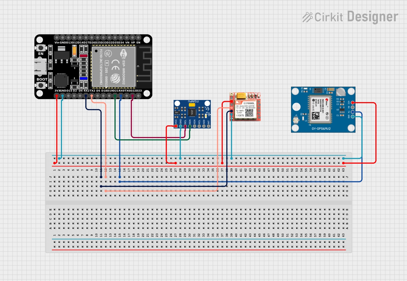
How to Use the Component in a Circuit

  1. Powering the Device: Connect the VCC pin to a 2.4V - 3.6V power source and the GND pin to the ground.
  2. Communication Setup: For I2C communication, connect SCL to the I2C clock and SDA to the I2C data. For SPI, connect SCLK, SDI, SDO, and NCS accordingly.
  3. Address Selection: The AD0/SDO pin can be used to set the I2C address. Connect it to VCC or GND to select between the two available addresses.
  4. Interrupts (Optional): The INT pin can be connected to an external interrupt on a microcontroller to trigger actions when data is ready or other events occur.

Important Considerations and Best Practices

  • Ensure that the power supply is within the specified voltage range to prevent damage.
  • Use pull-up resistors on the I2C lines if they are not built into the microcontroller.
  • For SPI communication, ensure that the NCS pin is kept high when the device is not in use.
  • When using the interrupt feature, configure the MPU9250/GY-91 registers to set up the interrupt conditions.

Example Code for Arduino UNO

#include <Wire.h>

// MPU9250 I2C address (depends on AD0 pin, check datasheet)
const int MPU9250_ADDRESS = 0x68;

void setup() {
  Wire.begin(); // Initialize I2C
  Serial.begin(9600); // Start serial communication at 9600 baud
  setupMPU9250(); // Setup MPU9250 registers for operation
}

void loop() {
  // Read sensor data and print it
  readSensorData();
  delay(100); // Delay for readability
}

void setupMPU9250() {
  // Write to the power management register to wake up the MPU9250
  writeMPU9250Register(MPU9250_ADDRESS, 0x6B, 0x00);
}

void writeMPU9250Register(byte address, byte reg, byte data) {
  Wire.beginTransmission(address);
  Wire.write(reg);
  Wire.write(data);
  Wire.endTransmission();
}

void readSensorData() {
  Wire.beginTransmission(MPU9250_ADDRESS);
  Wire.write(0x3B); // Starting register for accelerometer data
  Wire.endTransmission(false);
  Wire.requestFrom(MPU9250_ADDRESS, 14, true); // Request 14 bytes from the MPU9250

  // Read and process accelerometer, gyroscope, and temperature data
  // Accelerometer data
  int16_t ax = Wire.read() << 8 | Wire.read();
  int16_t ay = Wire.read() << 8 | Wire.read();
  int16_t az = Wire.read() << 8 | Wire.read();
  // Temperature data (not used in this example)
  Wire.read(); Wire.read();
  // Gyroscope data
  int16_t gx = Wire.read() << 8 | Wire.read();
  int16_t gy = Wire.read() << 8 | Wire.read();
  int16_t gz = Wire.read() << 8 | Wire.read();

  // Print the sensor data
  Serial.print("Accel: ");
  Serial.print("X="); Serial.print(ax);
  Serial.print(" Y="); Serial.print(ay);
  Serial.print(" Z="); Serial.println(az);
  Serial.print("Gyro: ");
  Serial.print("X="); Serial.print(gx);
  Serial.print(" Y="); Serial.print(gy);
  Serial.print(" Z="); Serial.println(gz);
}

Troubleshooting and FAQs

Common Issues

  • No Data Output: Ensure that the device is properly powered and that the I2C/SPI connections are correct.
  • Inaccurate Readings: Calibrate the sensor for your specific application environment.
  • Intermittent Connection: Check for loose connections and ensure that the pull-up resistors are in place for I2C.

Solutions and Tips for Troubleshooting

  • Power Supply Issues: Use a multimeter to verify the voltage at the VCC pin.
  • Communication Errors: Use an I2C scanner sketch to check if the MPU9250 is detected on the bus.
  • Sensor Calibration: Follow the manufacturer's guidelines for calibrating the gyroscope, accelerometer, and compass.

FAQs

Q: Can the MPU9250/GY-91 be used with both 3.3V and 5V microcontrollers? A: Yes, but ensure that the voltage levels for communication are compatible or use level shifters if necessary.

Q: How can I change the I2C address of the MPU9250? A: The I2C address can be changed by connecting the AD0/SDO pin to either VCC or GND.

Q: What is the default I2C address of the MPU9250? A: The default I2C address is 0x68 when AD0/SDO is connected to GND. It changes to 0x69 when connected to VCC.

Q: How do I interpret the raw data from the MPU9250? A: The raw data needs to be converted using the sensitivity levels specified in the datasheet. This will give you the actual measurements in the appropriate units (e.g., g for acceleration, °/sec for gyroscope, μT for magnetometer).