How to Use INA226: Examples, Pinouts, and Specs
Introduction
The INA226, manufactured by Sensor, is a high-side current shunt monitor with an integrated I2C interface. It is designed to measure voltage, current, and power in a wide range of applications. The device features a precision analog-to-digital converter (ADC) and operates with a supply voltage of 2.7V to 5.5V, making it ideal for battery-powered devices and energy monitoring systems.
Explore Projects Built with INA226

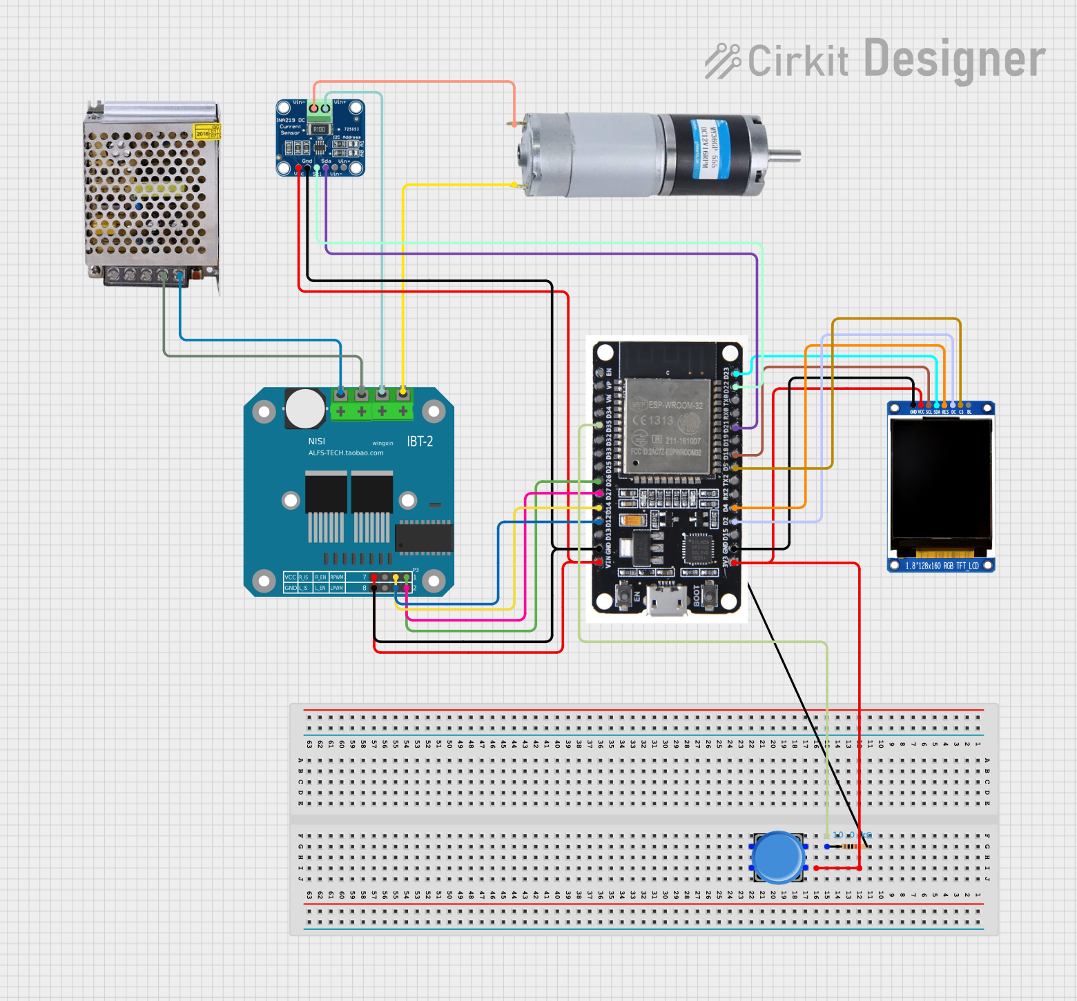


Explore Projects Built with INA226
Common Applications and Use Cases
- Battery management systems
- Power supply monitoring
- Solar inverters and energy meters
- Industrial automation
- IoT devices requiring power consumption tracking
Technical Specifications
The INA226 is a versatile and precise component. Below are its key technical details:
Key Specifications
| Parameter | Value |
|---|---|
| Supply Voltage (Vcc) | 2.7V to 5.5V |
| Input Voltage Range | 0V to 36V |
| Current Measurement Range | Configurable (based on shunt) |
| ADC Resolution | 16-bit |
| Communication Interface | I2C (up to 1 MHz) |
| Operating Temperature | -40°C to +125°C |
| Power Consumption | 330 µA (typical) |
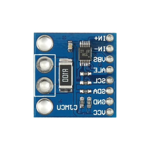
Pin Configuration and Descriptions
The INA226 is available in a small 10-pin VSSOP package. Below is the pinout and description:
| Pin Number | Pin Name | Description |
|---|---|---|
| 1 | VBUS | Voltage input to measure bus voltage |
| 2 | GND | Ground connection |
| 3 | SCL | I2C clock input |
| 4 | SDA | I2C data input/output |
| 5 | ALERT | Alert output (active low) for configurable thresholds |
| 6 | VSHUNT+ | Positive input for shunt resistor (current measurement) |
| 7 | VSHUNT- | Negative input for shunt resistor (current measurement) |
| 8 | VCC | Power supply input (2.7V to 5.5V) |
| 9, 10 | NC | No connection (leave floating or connect to ground for stability) |
Usage Instructions
The INA226 is straightforward to use in a circuit. Below are the steps and considerations for proper usage:
Connecting the INA226
- Power Supply: Connect the VCC pin to a 2.7V to 5.5V power source and the GND pin to ground.
- Voltage Measurement: Connect the VBUS pin to the voltage source you want to measure.
- Current Measurement: Place a shunt resistor between the VSHUNT+ and VSHUNT- pins. The INA226 measures the voltage drop across this resistor to calculate current.
- I2C Communication: Connect the SCL and SDA pins to the corresponding I2C lines of your microcontroller. Use pull-up resistors (typically 4.7kΩ) on these lines.
- Alert Pin (Optional): Configure the ALERT pin for overcurrent, overvoltage, or other threshold-based alerts.
Important Considerations
- Shunt Resistor Selection: Choose a shunt resistor with a low resistance value to minimize power loss but high enough to produce a measurable voltage drop.
- I2C Address: The INA226 has a configurable I2C address, allowing multiple devices on the same bus. Refer to the datasheet for address configuration details.
- Bypass Capacitor: Place a 0.1µF ceramic capacitor close to the VCC pin for power supply decoupling.
Example Code for Arduino UNO
Below is an example of how to interface the INA226 with an Arduino UNO to measure voltage and current:
#include <Wire.h>

// INA226 I2C address (default is 0x40, check datasheet for address configuration)
#define INA226_ADDRESS 0x40

// Register addresses
#define REG_BUS_VOLTAGE 0x02
#define REG_SHUNT_VOLTAGE 0x01

void setup() {
  Wire.begin(); // Initialize I2C communication
  Serial.begin(9600); // Initialize serial communication for debugging

  // Configure INA226 (e.g., calibration, averaging, etc.)
  configureINA226();
}

void loop() {
  float busVoltage = readBusVoltage(); // Read bus voltage
  float shuntVoltage = readShuntVoltage(); // Read shunt voltage
  float current = shuntVoltage / 0.1; // Calculate current (assuming 0.1Ω shunt resistor)

  // Print results to the serial monitor
  Serial.print("Bus Voltage: ");
  Serial.print(busVoltage);
  Serial.println(" V");

  Serial.print("Current: ");
  Serial.print(current);
  Serial.println(" A");

  delay(1000); // Wait 1 second before the next reading
}

void configureINA226() {
  Wire.beginTransmission(INA226_ADDRESS);
  Wire.write(0x00); // Configuration register
  Wire.write(0x45); // MSB of configuration (example value)
  Wire.write(0x27); // LSB of configuration (example value)
  Wire.endTransmission();
}

float readBusVoltage() {
  Wire.beginTransmission(INA226_ADDRESS);
  Wire.write(REG_BUS_VOLTAGE); // Bus voltage register
  Wire.endTransmission();

  Wire.requestFrom(INA226_ADDRESS, 2); // Request 2 bytes
  uint16_t rawData = (Wire.read() << 8) | Wire.read(); // Combine MSB and LSB
  return rawData * 0.00125; // Convert to volts (1.25mV per bit)
}

float readShuntVoltage() {
  Wire.beginTransmission(INA226_ADDRESS);
  Wire.write(REG_SHUNT_VOLTAGE); // Shunt voltage register
  Wire.endTransmission();

  Wire.requestFrom(INA226_ADDRESS, 2); // Request 2 bytes
  uint16_t rawData = (Wire.read() << 8) | Wire.read(); // Combine MSB and LSB
  return rawData * 0.0000025; // Convert to volts (2.5µV per bit)
}
Troubleshooting and FAQs
Common Issues
No I2C Communication:
- Ensure the SCL and SDA lines have proper pull-up resistors (4.7kΩ recommended).
- Verify the I2C address of the INA226 matches the one in your code.
- Check for loose or incorrect wiring.
Incorrect Voltage or Current Readings:
- Verify the shunt resistor value and ensure it is properly connected.
- Check the calibration settings in the INA226 configuration.
Alert Pin Not Functioning:
- Ensure the ALERT pin is configured correctly in the INA226 registers.
- Verify the threshold values for the alert condition.
Tips for Troubleshooting
- Use an I2C scanner sketch to confirm the INA226 is detected on the I2C bus.
- Double-check all connections and ensure there are no shorts or loose wires.
- Refer to the INA226 datasheet for detailed register descriptions and configuration options.