How to Use TP5100: Examples, Pinouts, and Specs
Introduction
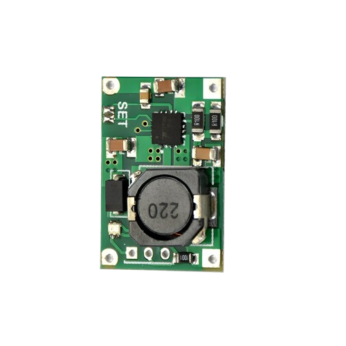
The TP5100, manufactured by Electronics Hut (Part ID: CHMOD), is a high-efficiency linear voltage regulator designed for low-dropout (LDO) applications. It ensures a stable output voltage with a minimal input-output voltage difference, making it ideal for battery-powered devices and other applications requiring efficient power management. Its compact design and robust performance make it a popular choice for portable electronics, IoT devices, and embedded systems.
Explore Projects Built with TP5100


Explore Projects Built with TP5100
Common Applications
- Battery-powered devices (e.g., smartphones, wearables)
- IoT devices and sensors
- Embedded systems requiring stable voltage regulation
- Power management in portable electronics
- Low-noise analog circuits
Technical Specifications
The TP5100 is designed to deliver reliable performance under a wide range of operating conditions. Below are its key technical specifications:
| Parameter | Value |
|---|---|
| Input Voltage Range | 4.5V to 18V |
| Output Voltage Range | 1.2V to 12V (adjustable) |
| Maximum Output Current | 2A |
| Dropout Voltage | 0.2V (at 1A load) |
| Efficiency | Up to 90% |
| Quiescent Current | 1.5mA (typical) |
| Operating Temperature | -40°C to +85°C |
| Package Type | SOP-8 |
Pin Configuration and Descriptions
The TP5100 features an 8-pin SOP package. Below is the pinout and description:
| Pin Number | Pin Name | Description |
|---|---|---|
| 1 | VIN | Input voltage pin. Connect to the power source (4.5V to 18V). |
| 2 | GND | Ground pin. Connect to the system ground. |
| 3 | VOUT | Regulated output voltage pin. Connect to the load. |
| 4 | FB | Feedback pin. Used to set the output voltage with an external resistor divider. |
| 5 | EN | Enable pin. High to enable the regulator, low to disable. |
| 6 | NC | No connection. Leave unconnected or grounded. |
| 7 | PG | Power Good pin. Indicates the status of the output voltage. |
| 8 | SS | Soft-start pin. Connect a capacitor to control the startup time. |
Usage Instructions
Using the TP5100 in a Circuit
To use the TP5100 in a circuit, follow these steps:
- Input Voltage: Connect the input voltage (VIN) to a power source within the range of 4.5V to 18V. Use a decoupling capacitor (e.g., 10µF) close to the VIN pin to reduce noise.
- Output Voltage: Connect the VOUT pin to the load. Use a capacitor (e.g., 22µF) near the VOUT pin to stabilize the output voltage.
- Feedback Resistor Divider: Use two resistors to set the desired output voltage. The formula is: [ V_{OUT} = V_{REF} \times \left(1 + \frac{R1}{R2}\right) ] where ( V_{REF} ) is typically 1.2V.
- Enable Pin: Pull the EN pin high (e.g., connect to VIN) to enable the regulator. Pull it low to disable.
- Soft-Start: Connect a capacitor to the SS pin to control the startup time. A larger capacitor results in a slower startup.
- Power Good: Use the PG pin to monitor the output voltage status. It goes high when the output voltage is stable.
Important Considerations
- Ensure the input voltage is at least 0.2V higher than the desired output voltage to maintain regulation.
- Use low-ESR capacitors for better stability and performance.
- Avoid exceeding the maximum input voltage (18V) or output current (2A) to prevent damage.
- Place all external components (e.g., capacitors, resistors) as close to the IC as possible to minimize noise and improve stability.
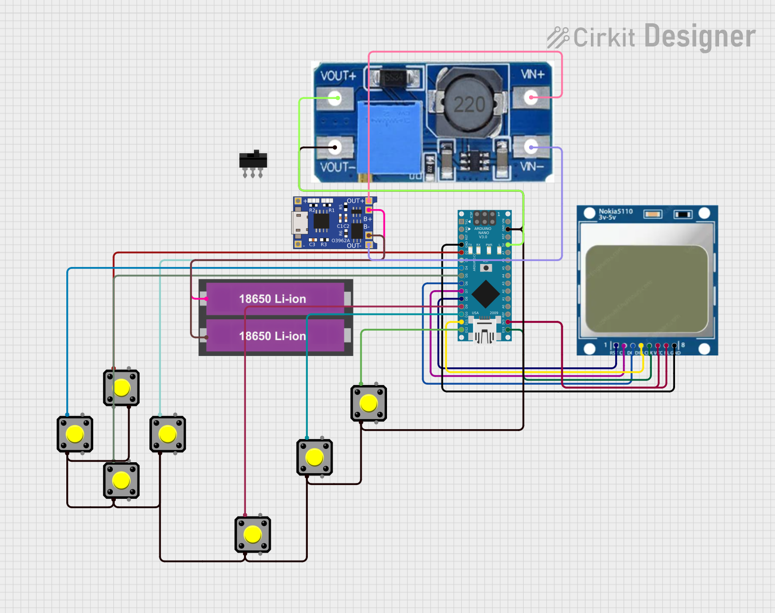
Example: Connecting TP5100 to an Arduino UNO
The TP5100 can be used to power an Arduino UNO by regulating a higher input voltage (e.g., 12V) down to 5V. Below is an example circuit and Arduino code:
Circuit Setup
- Connect a 12V power source to the VIN pin of the TP5100.
- Set the output voltage to 5V using a resistor divider on the FB pin.
- Connect the VOUT pin to the 5V pin of the Arduino UNO.
- Pull the EN pin high to enable the regulator.
Arduino Code Example
// Example code to read a sensor powered by the TP5100 regulator
// Ensure the TP5100 output is set to 5V for the Arduino UNO

const int sensorPin = A0; // Analog pin connected to the sensor
int sensorValue = 0;      // Variable to store the sensor reading

void setup() {
  Serial.begin(9600); // Initialize serial communication at 9600 baud
  pinMode(sensorPin, INPUT); // Set the sensor pin as input
}

void loop() {
  sensorValue = analogRead(sensorPin); // Read the sensor value
  Serial.print("Sensor Value: ");
  Serial.println(sensorValue); // Print the sensor value to the Serial Monitor
  delay(1000); // Wait for 1 second before the next reading
}
Troubleshooting and FAQs
Common Issues and Solutions
No Output Voltage
- Cause: The EN pin is not pulled high.
- Solution: Ensure the EN pin is connected to VIN or another high signal.
Output Voltage is Unstable
- Cause: Insufficient decoupling or output capacitance.
- Solution: Use low-ESR capacitors (e.g., 10µF at VIN and 22µF at VOUT).
Overheating
- Cause: Excessive load current or insufficient heat dissipation.
- Solution: Ensure the load current does not exceed 2A. Use a heatsink or improve PCB thermal design.
Incorrect Output Voltage
- Cause: Incorrect resistor values in the feedback network.
- Solution: Verify the resistor values and recalculate using the formula: [ V_{OUT} = V_{REF} \times \left(1 + \frac{R1}{R2}\right) ]
FAQs
Can the TP5100 be used with a 3.3V system?
- Yes, the output voltage can be set to 3.3V using the appropriate feedback resistor values.
What is the maximum input voltage for the TP5100?
- The maximum input voltage is 18V. Exceeding this value may damage the component.
How do I calculate the soft-start time?
- The soft-start time is determined by the capacitor connected to the SS pin. Refer to the datasheet for the exact formula.
Is the TP5100 suitable for audio applications?
- Yes, its low dropout and low noise characteristics make it suitable for low-noise analog circuits, including audio applications.