Cirkit Designer Logo
Cirkit Designer
Your all-in-one circuit design IDE
Home / 
Component Documentation

How to Use STM32F0: Examples, Pinouts, and Specs

Image of STM32F0
Cirkit Designer LogoDesign with STM32F0 in Cirkit Designer

Introduction

The STM32F0 series represents a range of 32-bit microcontrollers designed around the ARM Cortex-M0 processor core. These microcontrollers are known for their balance of performance and power efficiency, which makes them an ideal choice for various embedded applications. Common use cases include industrial controls, consumer electronics, home automation, and medical devices.

Explore Projects Built with STM32F0

Use Cirkit Designer to design, explore, and prototype these projects online. Some projects support real-time simulation. Click "Open Project" to start designing instantly!
STM32F103C8T6 Bluetooth-Controlled Arcade Joystick Interface
Image of RC카 조이스틱: A project utilizing STM32F0 in a practical application
This circuit features an STM32F103C8T6 microcontroller interfaced with a Bluetooth HC-06 module for wireless communication and an Adafruit Arcade Joystick for user input. The microcontroller's pins B0 and B10 are connected to the TXD and RXD pins of the Bluetooth module, enabling serial communication, while pins B14 and B15 interface with the joystick's directional controls. The circuit is powered by a battery, with power distribution managed through the microcontroller's 3.3V pin and common ground connections.
Cirkit Designer LogoOpen Project in Cirkit Designer
Solar-Powered STM32-Based Automation System with Matrix Keypad and RTC
Image of soloar cleaner : A project utilizing STM32F0 in a practical application
This circuit features an STM32F103C8T6 microcontroller interfaced with a membrane matrix keypad for input, an RTC DS3231 for real-time clock functionality, and a 16x2 I2C LCD for display. It controls four 12V geared motors through two MD20 CYTRON motor drivers, with the motor power supplied by a 12V battery regulated by a buck converter. The battery is charged via a solar panel connected through a solar charge controller, ensuring a renewable energy source for the system.
Cirkit Designer LogoOpen Project in Cirkit Designer
STM32F103C8T6 Battery-Powered LED Indicator Circuit
Image of Assigment.2: A project utilizing STM32F0 in a practical application
This circuit features an STM32F103C8T6 microcontroller powered by a 3.3V battery, which controls a red LED. The LED is connected to pin A1 of the microcontroller through a 10-ohm resistor to limit the current.
Cirkit Designer LogoOpen Project in Cirkit Designer
STM32F103C8T6-Based Water Level Monitoring and Communication System with SIM900A and LoRa Connectivity
Image of water level: A project utilizing STM32F0 in a practical application
This circuit features a microcontroller (STM32F103C8T6) interfaced with a SIM900A GSM module, an HC-SR04 ultrasonic sensor, a water level sensor, and a LoRa Ra-02 SX1278 module for long-range communication. The STM32F103C8T6 is configured to communicate with the GSM module and LoRa module via serial connections, and it reads data from the ultrasonic and water level sensors. An FTDI Programmer is connected for programming and serial communication with the microcontroller.
Cirkit Designer LogoOpen Project in Cirkit Designer

Explore Projects Built with STM32F0

Use Cirkit Designer to design, explore, and prototype these projects online. Some projects support real-time simulation. Click "Open Project" to start designing instantly!
Image of RC카 조이스틱: A project utilizing STM32F0 in a practical application
STM32F103C8T6 Bluetooth-Controlled Arcade Joystick Interface
This circuit features an STM32F103C8T6 microcontroller interfaced with a Bluetooth HC-06 module for wireless communication and an Adafruit Arcade Joystick for user input. The microcontroller's pins B0 and B10 are connected to the TXD and RXD pins of the Bluetooth module, enabling serial communication, while pins B14 and B15 interface with the joystick's directional controls. The circuit is powered by a battery, with power distribution managed through the microcontroller's 3.3V pin and common ground connections.
Cirkit Designer LogoOpen Project in Cirkit Designer
Image of soloar cleaner : A project utilizing STM32F0 in a practical application
Solar-Powered STM32-Based Automation System with Matrix Keypad and RTC
This circuit features an STM32F103C8T6 microcontroller interfaced with a membrane matrix keypad for input, an RTC DS3231 for real-time clock functionality, and a 16x2 I2C LCD for display. It controls four 12V geared motors through two MD20 CYTRON motor drivers, with the motor power supplied by a 12V battery regulated by a buck converter. The battery is charged via a solar panel connected through a solar charge controller, ensuring a renewable energy source for the system.
Cirkit Designer LogoOpen Project in Cirkit Designer
Image of Assigment.2: A project utilizing STM32F0 in a practical application
STM32F103C8T6 Battery-Powered LED Indicator Circuit
This circuit features an STM32F103C8T6 microcontroller powered by a 3.3V battery, which controls a red LED. The LED is connected to pin A1 of the microcontroller through a 10-ohm resistor to limit the current.
Cirkit Designer LogoOpen Project in Cirkit Designer
Image of water level: A project utilizing STM32F0 in a practical application
STM32F103C8T6-Based Water Level Monitoring and Communication System with SIM900A and LoRa Connectivity
This circuit features a microcontroller (STM32F103C8T6) interfaced with a SIM900A GSM module, an HC-SR04 ultrasonic sensor, a water level sensor, and a LoRa Ra-02 SX1278 module for long-range communication. The STM32F103C8T6 is configured to communicate with the GSM module and LoRa module via serial connections, and it reads data from the ultrasonic and water level sensors. An FTDI Programmer is connected for programming and serial communication with the microcontroller.
Cirkit Designer LogoOpen Project in Cirkit Designer

Technical Specifications

Key Technical Details

  • Core: ARM Cortex-M0 processor
  • Operating Voltage: 2.0 V to 3.6 V
  • I/O Pins: Up to 80 GPIOs with various multiplexed functions
  • Clock Frequency: Up to 48 MHz
  • Flash Memory: Up to 256 KB (depending on the model)
  • SRAM: Up to 32 KB (depending on the model)
  • Timers: Multiple 16-bit and 32-bit timers
  • Communication Interfaces: I2C, SPI, UART, CAN, USB
  • Analog: Up to 16-channel 12-bit ADC, DAC
  • Debugging: Serial Wire Debug (SWD)

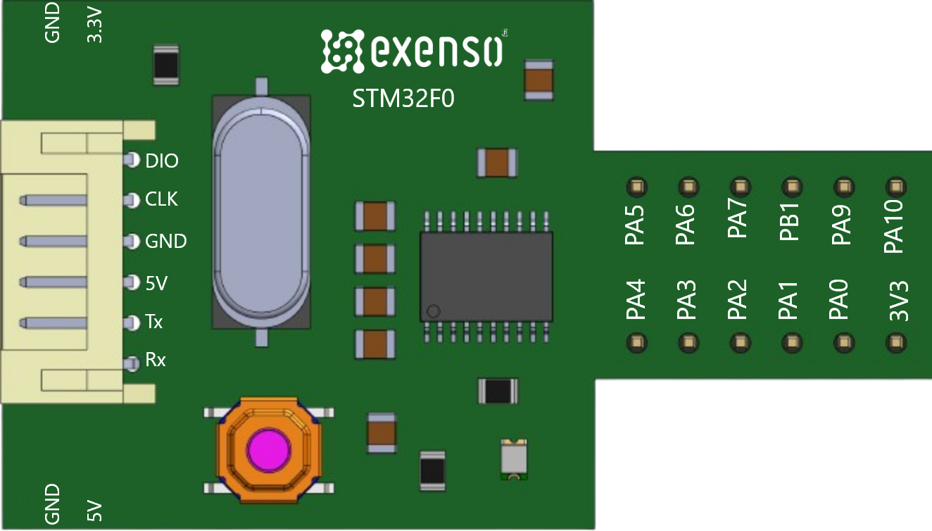
Pin Configuration and Descriptions

Pin Number Name Description
1 VDD Power supply
2 VSS Ground reference
3 NRST Reset input
... ... ...
n VBAT Battery backup for RTC

Note: The pin configuration varies by package and model. Refer to the specific datasheet for your STM32F0 model for the complete pinout.

Usage Instructions

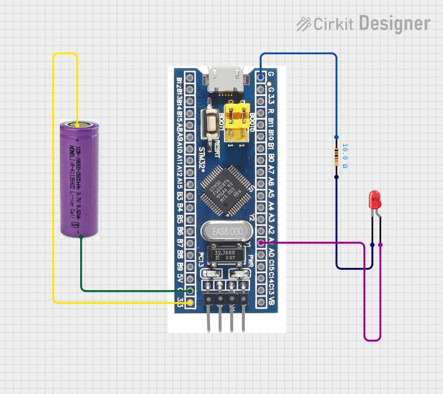
Integrating STM32F0 into a Circuit

  1. Power Supply: Connect a regulated power source to the VDD pins and ground to the VSS pins. Ensure the voltage is within the specified range.
  2. Clock Source: Configure the clock source. You can use an external crystal or the internal oscillator.
  3. Programming: Use the SWD interface for programming the microcontroller.
  4. I/O Configuration: Set up the GPIO pins according to your application's needs, considering the multiplexed functions.

Best Practices

  • Use bypass capacitors near the power supply pins to filter noise.
  • Implement proper ESD protection for all I/O pins.
  • Follow the guidelines for PCB layout, including trace impedance control and thermal management.
  • Ensure firmware is developed with proper consideration for interrupt handling and low-power modes.

Troubleshooting and FAQs

Common Issues

  • Microcontroller not responding: Verify the power supply, check for proper clock configuration, and ensure the SWD interface is correctly connected.
  • I/O malfunction: Check the pin configuration and ensure that the GPIOs are not being overloaded.
  • Unexpected resets: Monitor the voltage levels to rule out power supply issues and check for any watchdog timer misconfigurations.

FAQs

  • Q: How do I program the STM32F0? A: You can program it using the SWD interface with tools like ST-Link or a compatible programmer/debugger.

  • Q: Can the STM32F0 series operate in low-power modes? A: Yes, the STM32F0 series has several low-power modes to reduce power consumption during idle periods.

  • Q: What development environments are compatible with STM32F0? A: Various environments like STM32CubeIDE, Keil MDK, IAR EWARM, and others that support ARM Cortex-M development.

For more detailed troubleshooting, refer to the manufacturer's documentation and community forums.

Example Code for Arduino UNO Interfacing

// Example code for interfacing STM32F0 with Arduino UNO via UART
#include <SoftwareSerial.h>

SoftwareSerial stm32Serial(10, 11); // RX, TX

void setup() {
  // Start the hardware serial communication
  Serial.begin(9600);
  // Start the software serial communication
  stm32Serial.begin(9600);
  Serial.println("STM32F0 UART Interface Example");
}

void loop() {
  if (stm32Serial.available()) {
    // Read data from STM32F0
    char data = stm32Serial.read();
    // Send the data to the Serial Monitor
    Serial.print(data);
  }

  if (Serial.available()) {
    // Read data from Serial Monitor
    char data = Serial.read();
    // Send the data to the STM32F0
    stm32Serial.write(data);
  }
}

Note: This example assumes that the STM32F0 has been programmed to communicate via UART. The pins 10 and 11 on the Arduino UNO are used for software serial communication.

Remember to consult the STM32F0 reference manual and datasheets for specific details on programming and interfacing with other devices.