Cirkit Designer Logo
Cirkit Designer
Your all-in-one circuit design IDE
Home / 
Component Documentation

How to Use Current Sensor 0-30A ACS712 : Examples, Pinouts, and Specs

Image of Current Sensor 0-30A ACS712
Cirkit Designer LogoDesign with Current Sensor 0-30A ACS712 in Cirkit Designer

Introduction

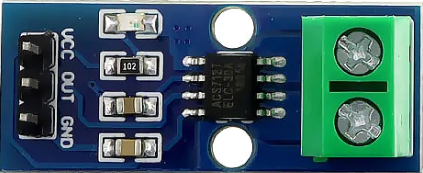
The ACS712 is a Hall effect-based current sensor capable of measuring both AC and DC currents up to ±30A. It outputs an analog voltage proportional to the current flowing through it, allowing for precise current monitoring. The sensor is compact, easy to use, and widely employed in applications such as power monitoring, motor control, battery management, and overcurrent protection systems.

Explore Projects Built with Current Sensor 0-30A ACS712

Use Cirkit Designer to design, explore, and prototype these projects online. Some projects support real-time simulation. Click "Open Project" to start designing instantly!
Wemos S2 Mini Controlled Smart Device with OLED Display, Thermal Printing, and RGB LED Strip
Image of DT NEA - Noah Patel: A project utilizing Current Sensor 0-30A ACS712  in a practical application
This circuit features a Wemos S2 Mini microcontroller that controls a WS2812 RGB LED strip and communicates with a 0.96" OLED display and a 58mm mini thermal printer. The ACS712 Current Sensor is interfaced with the microcontroller to monitor current, and power is managed by a CD42 BMS connected to two 18650 Li-ion batteries, with a USB-C PD Trigger Board for power delivery. The circuit is designed for visual output (LED strip, OLED display), printing capabilities, and current sensing, likely for a portable, battery-powered monitoring and display device.
Cirkit Designer LogoOpen Project in Cirkit Designer
ESP32-Based Current Monitoring and Temperature Sensing System
Image of SISTEMA DE MONITOREO: A project utilizing Current Sensor 0-30A ACS712  in a practical application
This circuit is designed to measure current using an ACS712 Current Sensor and temperature using a DS18B20 sensor, with an ESP32 microcontroller to process and possibly communicate the sensor data. The ACS712 sensor output is connected to one of the ESP32's analog input pins (D34), while the DS18B20's signal line is interfaced with a digital input pin (D23) through a pull-up resistor (4.7k Ohms). The ESP32 is powered through its Vin pin, and both sensors share a common ground with the ESP32.
Cirkit Designer LogoOpen Project in Cirkit Designer
ESP32-Controlled Smart Lighting System with Power Monitoring
Image of Energy Monitoring System: A project utilizing Current Sensor 0-30A ACS712  in a practical application
This circuit appears to be a multi-channel current monitoring system using several ACS712 current sensors to measure the current through different loads, likely bulbs connected to a 220V power source. The current readings from the sensors are digitized by an Adafruit ADS1115 16-bit ADC, which interfaces with an ESP32 microcontroller via I2C communication for further processing or telemetry. A buck converter is used to step down the voltage to power the ESP32 and the sensors, and the system is powered through a 2.1mm DC barrel jack, indicating it is designed for external power supply.
Cirkit Designer LogoOpen Project in Cirkit Designer
ESP32-Based Smart Power Monitoring System with OLED Display and Wi-Fi Connectivity
Image of Circle4Life test: A project utilizing Current Sensor 0-30A ACS712  in a practical application
This circuit is a monitoring system using an ESP32 microcontroller to read data from multiple ACS712 current sensors and DC voltage sensors, displaying the information on a 0.96" OLED screen. The system also includes pushbuttons for user interaction and connects to WiFi for data transmission.
Cirkit Designer LogoOpen Project in Cirkit Designer

Explore Projects Built with Current Sensor 0-30A ACS712

Use Cirkit Designer to design, explore, and prototype these projects online. Some projects support real-time simulation. Click "Open Project" to start designing instantly!
Image of DT NEA - Noah Patel: A project utilizing Current Sensor 0-30A ACS712  in a practical application
Wemos S2 Mini Controlled Smart Device with OLED Display, Thermal Printing, and RGB LED Strip
This circuit features a Wemos S2 Mini microcontroller that controls a WS2812 RGB LED strip and communicates with a 0.96" OLED display and a 58mm mini thermal printer. The ACS712 Current Sensor is interfaced with the microcontroller to monitor current, and power is managed by a CD42 BMS connected to two 18650 Li-ion batteries, with a USB-C PD Trigger Board for power delivery. The circuit is designed for visual output (LED strip, OLED display), printing capabilities, and current sensing, likely for a portable, battery-powered monitoring and display device.
Cirkit Designer LogoOpen Project in Cirkit Designer
Image of SISTEMA DE MONITOREO: A project utilizing Current Sensor 0-30A ACS712  in a practical application
ESP32-Based Current Monitoring and Temperature Sensing System
This circuit is designed to measure current using an ACS712 Current Sensor and temperature using a DS18B20 sensor, with an ESP32 microcontroller to process and possibly communicate the sensor data. The ACS712 sensor output is connected to one of the ESP32's analog input pins (D34), while the DS18B20's signal line is interfaced with a digital input pin (D23) through a pull-up resistor (4.7k Ohms). The ESP32 is powered through its Vin pin, and both sensors share a common ground with the ESP32.
Cirkit Designer LogoOpen Project in Cirkit Designer
Image of Energy Monitoring System: A project utilizing Current Sensor 0-30A ACS712  in a practical application
ESP32-Controlled Smart Lighting System with Power Monitoring
This circuit appears to be a multi-channel current monitoring system using several ACS712 current sensors to measure the current through different loads, likely bulbs connected to a 220V power source. The current readings from the sensors are digitized by an Adafruit ADS1115 16-bit ADC, which interfaces with an ESP32 microcontroller via I2C communication for further processing or telemetry. A buck converter is used to step down the voltage to power the ESP32 and the sensors, and the system is powered through a 2.1mm DC barrel jack, indicating it is designed for external power supply.
Cirkit Designer LogoOpen Project in Cirkit Designer
Image of Circle4Life test: A project utilizing Current Sensor 0-30A ACS712  in a practical application
ESP32-Based Smart Power Monitoring System with OLED Display and Wi-Fi Connectivity
This circuit is a monitoring system using an ESP32 microcontroller to read data from multiple ACS712 current sensors and DC voltage sensors, displaying the information on a 0.96" OLED screen. The system also includes pushbuttons for user interaction and connects to WiFi for data transmission.
Cirkit Designer LogoOpen Project in Cirkit Designer

Common Applications:

  • Power consumption monitoring in appliances
  • Overcurrent detection in circuits
  • Battery charge and discharge monitoring
  • Motor current sensing in robotics
  • Renewable energy systems (e.g., solar inverters)

Technical Specifications

Below are the key technical details of the ACS712 0-30A current sensor:

Parameter Value
Supply Voltage (Vcc) 4.5V to 5.5V
Measurement Range ±30A
Sensitivity 66mV/A
Output Voltage Range 0.5V to 4.5V
Zero Current Output ~2.5V
Response Time 5 µs
Bandwidth 80 kHz
Operating Temperature -40°C to +85°C

Pin Configuration

The ACS712 module typically has three pins for connection:

Pin Name Description
1 VCC Power supply input (4.5V to 5.5V)
2 OUT Analog voltage output proportional to the current being measured
3 GND Ground connection

Usage Instructions

How to Use the ACS712 in a Circuit

  1. Power the Sensor: Connect the VCC pin to a 5V power supply and the GND pin to the ground of your circuit.
  2. Connect the Load: Pass the current-carrying wire through the sensor's onboard current path (IP+ and IP- terminals). Ensure the current does not exceed ±30A.
  3. Read the Output: Connect the OUT pin to an analog input pin of a microcontroller (e.g., Arduino) to read the voltage output. The output voltage is proportional to the current flowing through the sensor.

Important Considerations:

  • Calibration: The sensor's output voltage at zero current is approximately 2.5V. You may need to calibrate your system to account for small offsets.
  • Noise Filtering: Add a capacitor (e.g., 0.1 µF) between the OUT pin and GND to reduce noise in the output signal.
  • Current Direction: Positive current flows from IP+ to IP-, while negative current flows in the opposite direction.
  • Avoid Overcurrent: Ensure the current through the sensor does not exceed ±30A to prevent damage.

Example Code for Arduino UNO

The following code demonstrates how to use the ACS712 with an Arduino UNO to measure current:

// Include necessary libraries (if any)

// Define the analog pin connected to the ACS712 OUT pin
const int sensorPin = A0;

// Define the sensitivity of the ACS712 (66mV/A for 30A version)
const float sensitivity = 0.066; // Sensitivity in V/A

// Define the zero-current output voltage (2.5V for ACS712)
const float zeroCurrentVoltage = 2.5;

void setup() {
  Serial.begin(9600); // Initialize serial communication
}

void loop() {
  // Read the analog value from the sensor
  int sensorValue = analogRead(sensorPin);

  // Convert the analog value to voltage (5V reference, 10-bit ADC)
  float sensorVoltage = sensorValue * (5.0 / 1023.0);

  // Calculate the current in Amperes
  float current = (sensorVoltage - zeroCurrentVoltage) / sensitivity;

  // Print the current value to the Serial Monitor
  Serial.print("Current: ");
  Serial.print(current);
  Serial.println(" A");

  delay(1000); // Wait for 1 second before the next reading
}

Notes:

  • Ensure the Arduino's analog reference voltage is stable for accurate readings.
  • Use proper wiring and connectors to handle high currents safely.

Troubleshooting and FAQs

Common Issues and Solutions:

  1. No Output or Incorrect Readings:

    • Verify that the VCC and GND pins are properly connected to a 5V power supply.
    • Check the wiring of the current-carrying conductor through the sensor.
  2. High Noise in Output:

    • Add a decoupling capacitor (e.g., 0.1 µF) between the OUT pin and GND.
    • Use shielded cables for the current-carrying conductor to reduce electromagnetic interference.
  3. Output Voltage Stuck at 2.5V:

    • Ensure there is current flowing through the sensor. If not, the output will remain at the zero-current voltage (2.5V).
  4. Overheating of the Sensor:

    • Check if the current exceeds the sensor's maximum rating of ±30A. Reduce the load if necessary.

FAQs:

Q1: Can the ACS712 measure both AC and DC currents?
Yes, the ACS712 can measure both AC and DC currents. The output voltage will vary proportionally with the instantaneous current.

Q2: How do I calculate the current from the sensor's output voltage?
Use the formula:
Current (A) = (Output Voltage - Zero Current Voltage) / Sensitivity
For the 30A version, the sensitivity is 66mV/A, and the zero-current voltage is approximately 2.5V.

Q3: Can I use the ACS712 with a 3.3V microcontroller?
Yes, but ensure the sensor is powered with 5V, and use a voltage divider or level shifter to scale the output voltage to the 3.3V range.

Q4: What is the maximum current the ACS712 can handle?
The ACS712 30A version can measure currents up to ±30A. Exceeding this limit may damage the sensor.

By following this documentation, you can effectively integrate the ACS712 current sensor into your projects for accurate current measurement and monitoring.