Cirkit Designer
Your all-in-one circuit design IDE
Home /
Component Documentation
How to Use GPS for lora: Examples, Pinouts, and Specs

Introduction
The GPS for LoRa module, manufactured by Bigboss, is a high-performance GPS module specifically designed for integration with long-range communication systems utilizing LoRa technology. This module combines precise location tracking with the ability to transmit data over extended distances, making it ideal for applications requiring reliable geolocation and low-power, long-range communication.
Explore Projects Built with GPS for lora
ESP8266 NodeMCU with GPS and LoRa Connectivity

This circuit comprises an ESP8266 NodeMCU microcontroller interfaced with a LoRa Ra-02 SX1278 module for long-range communication and a GPS NEO 6M module for location tracking. The ESP8266 reads GPS data via UART and transmits it using the LoRa module, which is connected via SPI. A 3.7v battery powers the system, making it suitable for remote tracking applications.
Arduino UNO and LoRa GPS Tracker with OLED Display
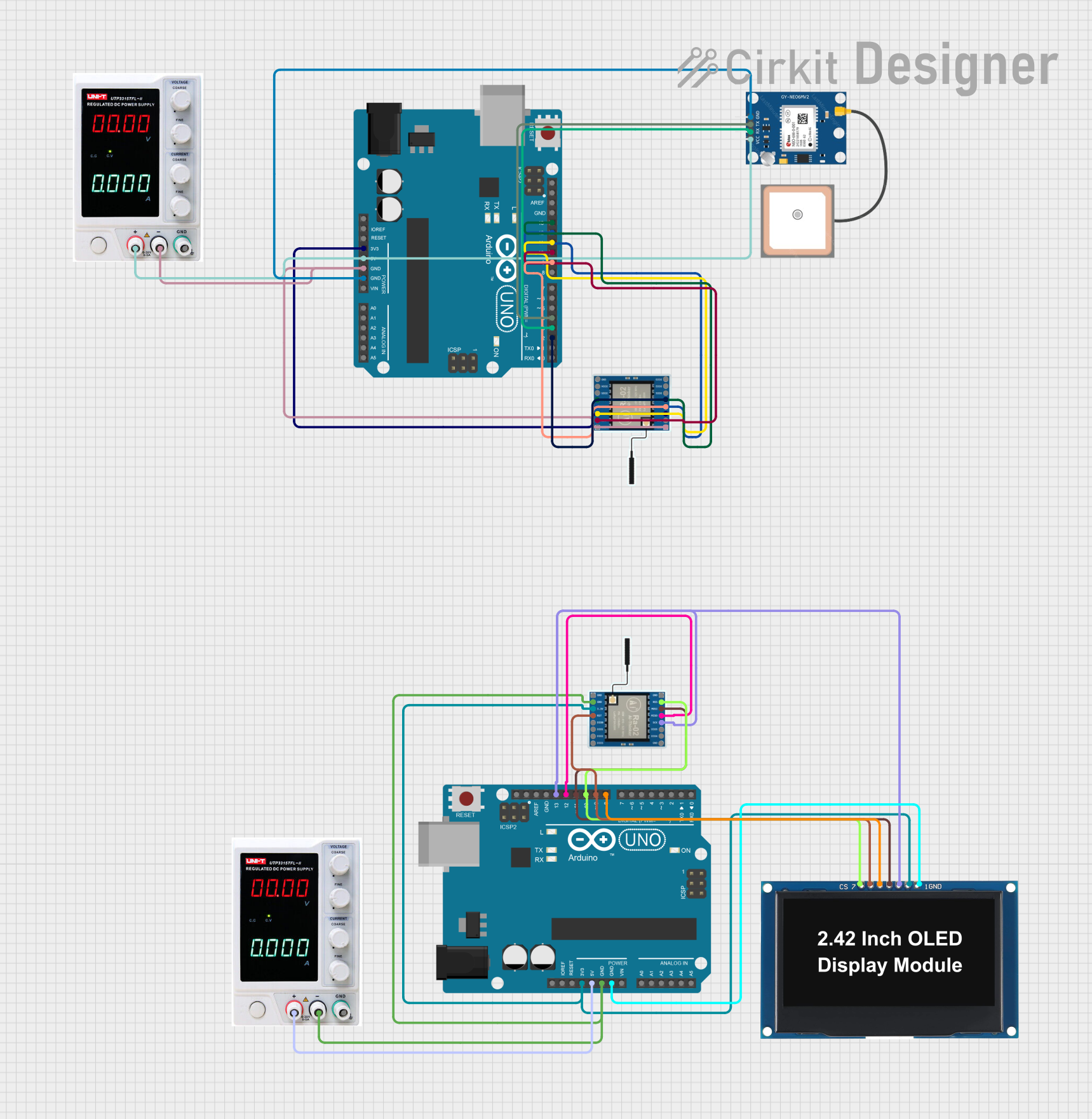
This circuit consists of two Arduino UNO microcontrollers, each interfaced with a LoRa Ra-02 SX1278 module for wireless communication. One Arduino is connected to a GPS NEO 6M module to transmit location data via LoRa, while the other Arduino receives the data and displays it on an OLED display.
Arduino UNO-Based GPS Tracker with LoRa Communication and ADXL345 Sensor
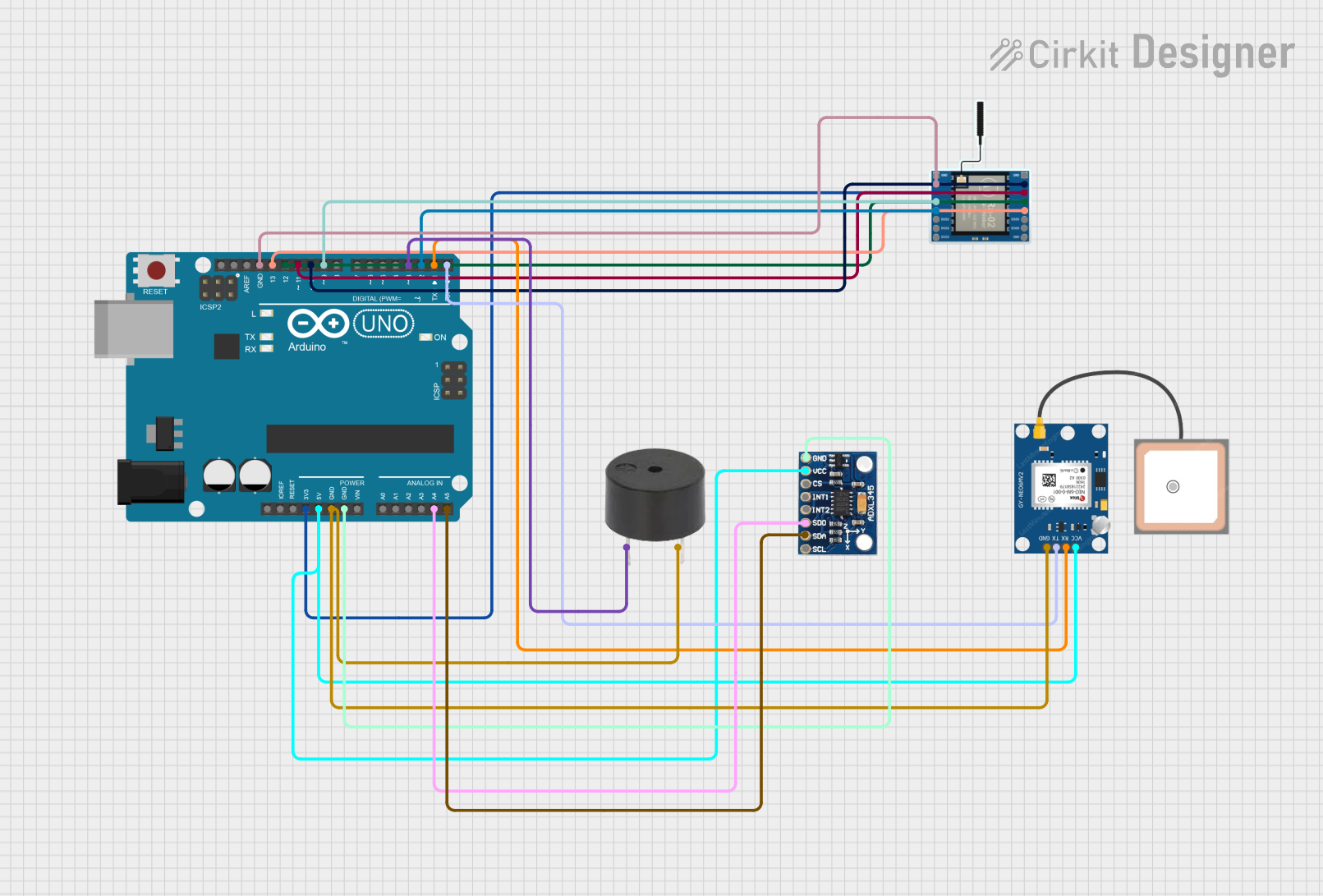
This circuit integrates an Arduino UNO with a LoRa Ra-02 SX1278 module for wireless communication, a GPS NEO 6M module for location tracking, an ADXL345 accelerometer for motion sensing, and a buzzer for audio alerts. The Arduino UNO serves as the central controller, interfacing with the LoRa module via SPI, the GPS module via serial communication, and the ADXL345 via I2C.
Arduino Nano Based GPS Tracker with LoRa Communication and LED Indicator
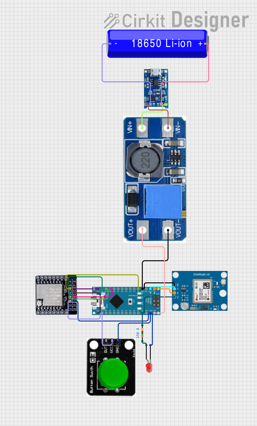
This circuit features an Arduino Nano interfaced with a Neo 6M GPS Module for location tracking and a LORA_RA02 module for long-range communication. The Arduino is powered by a 18650 Li-ion battery through a lipo battery charger module and a step-up boost power converter, ensuring a stable voltage supply. Additionally, the circuit includes a red LED with a current-limiting resistor and a green button, likely for user interaction and status indication.
Explore Projects Built with GPS for lora
ESP8266 NodeMCU with GPS and LoRa Connectivity
This circuit comprises an ESP8266 NodeMCU microcontroller interfaced with a LoRa Ra-02 SX1278 module for long-range communication and a GPS NEO 6M module for location tracking. The ESP8266 reads GPS data via UART and transmits it using the LoRa module, which is connected via SPI. A 3.7v battery powers the system, making it suitable for remote tracking applications.
Arduino UNO and LoRa GPS Tracker with OLED Display
This circuit consists of two Arduino UNO microcontrollers, each interfaced with a LoRa Ra-02 SX1278 module for wireless communication. One Arduino is connected to a GPS NEO 6M module to transmit location data via LoRa, while the other Arduino receives the data and displays it on an OLED display.
Arduino UNO-Based GPS Tracker with LoRa Communication and ADXL345 Sensor
This circuit integrates an Arduino UNO with a LoRa Ra-02 SX1278 module for wireless communication, a GPS NEO 6M module for location tracking, an ADXL345 accelerometer for motion sensing, and a buzzer for audio alerts. The Arduino UNO serves as the central controller, interfacing with the LoRa module via SPI, the GPS module via serial communication, and the ADXL345 via I2C.
Arduino Nano Based GPS Tracker with LoRa Communication and LED Indicator
This circuit features an Arduino Nano interfaced with a Neo 6M GPS Module for location tracking and a LORA_RA02 module for long-range communication. The Arduino is powered by a 18650 Li-ion battery through a lipo battery charger module and a step-up boost power converter, ensuring a stable voltage supply. Additionally, the circuit includes a red LED with a current-limiting resistor and a green button, likely for user interaction and status indication.
Common Applications and Use Cases
- Asset tracking in remote or rural areas
- IoT devices requiring geolocation and long-range communication
- Environmental monitoring systems
- Fleet management and logistics
- Smart agriculture and precision farming
Technical Specifications
Key Technical Details
| Parameter | Specification |
|---|---|
| Manufacturer | Bigboss |
| Part ID | GPS for LoRa |
| Input Voltage | 3.3V to 5V |
| Operating Current | 20mA (typical) |
| Communication Protocol | UART (9600 baud rate by default) |
| Positioning Accuracy | ±2.5 meters |
| Cold Start Time | < 35 seconds |
| Hot Start Time | < 1 second |
| Operating Temperature | -40°C to +85°C |
| Dimensions | 25mm x 25mm x 5mm |
| Antenna | External, active antenna supported |
Pin Configuration and Descriptions
| Pin Number | Pin Name | Description |
|---|---|---|
| 1 | VCC | Power supply input (3.3V to 5V). |
| 2 | GND | Ground connection. |
| 3 | TX | UART Transmit pin. Sends GPS data to the host microcontroller or device. |
| 4 | RX | UART Receive pin. Receives configuration commands from the host device. |
| 5 | PPS | Pulse Per Second output for precise timing synchronization. |
| 6 | EN | Enable pin. Pull high to activate the module, low to disable. |
Usage Instructions
How to Use the Component in a Circuit
- Power Supply: Connect the VCC pin to a 3.3V or 5V power source and the GND pin to ground.
- UART Communication: Connect the TX pin of the GPS module to the RX pin of your microcontroller (e.g., Arduino UNO) and the RX pin of the GPS module to the TX pin of the microcontroller.
- Antenna: Attach an active external antenna to the module for optimal GPS signal reception.
- Enable Pin: Ensure the EN pin is pulled high to activate the module.
- Data Parsing: The module outputs NMEA sentences (e.g., GPGGA, GPRMC) via the UART interface. Use a microcontroller or software to parse this data for location information.
Important Considerations and Best Practices
- Antenna Placement: Place the antenna in an open area with minimal obstructions for better GPS signal reception.
- Power Supply: Use a stable power source to avoid fluctuations that may affect GPS performance.
- UART Configuration: Ensure the UART baud rate is set to 9600 (default) on your microcontroller.
- PPS Pin: Use the PPS pin for applications requiring precise timing, such as synchronization in IoT networks.
- LoRa Integration: Pair the GPS module with a LoRa transceiver module to transmit location data over long distances.
Example Code for Arduino UNO
Below is an example of how to interface the GPS for LoRa module with an Arduino UNO to read and display GPS data.
#include <SoftwareSerial.h>

// Define RX and TX pins for SoftwareSerial
SoftwareSerial gpsSerial(4, 3); // RX = Pin 4, TX = Pin 3

void setup() {
  Serial.begin(9600); // Initialize Serial Monitor at 9600 baud
  gpsSerial.begin(9600); // Initialize GPS module at 9600 baud

  Serial.println("GPS for LoRa Module Test");
}

void loop() {
  // Check if data is available from the GPS module
  while (gpsSerial.available()) {
    char gpsData = gpsSerial.read(); // Read one character from GPS module
    Serial.print(gpsData); // Print the character to Serial Monitor

    // Note: GPS data is output as NMEA sentences. Use a GPS library like TinyGPS++
    // to parse and extract useful information such as latitude, longitude, etc.
  }
}
Troubleshooting and FAQs
Common Issues and Solutions
| Issue | Possible Cause | Solution |
|---|---|---|
| No GPS data received | Incorrect UART connection | Verify TX and RX connections between the GPS module and microcontroller. |
| GPS module not powering on | Insufficient or unstable power supply | Ensure the power supply is within the 3.3V to 5V range and is stable. |
| Poor GPS signal reception | Antenna placement issue | Place the antenna in an open area with a clear view of the sky. |
| Long time to acquire GPS fix | Cold start or weak signal environment | Wait for the module to complete a cold start or move to a better location. |
| Data appears garbled in Serial Monitor | Incorrect baud rate | Set the Serial Monitor and GPS module to the same baud rate (9600). |
FAQs
Can this module be used indoors?
- While the module may work indoors, GPS signal reception is significantly weaker. Use it in open areas for best results.
What type of antenna is recommended?
- An active external antenna is recommended for optimal performance.
Can I change the default baud rate?
- Yes, the baud rate can be changed using specific configuration commands sent via the UART interface.
Is this module compatible with other microcontrollers?
- Yes, the module is compatible with any microcontroller that supports UART communication, including Arduino, ESP32, and Raspberry Pi.
How do I integrate this module with a LoRa transceiver?
- Use the GPS module to obtain location data and transmit it via the LoRa transceiver using the microcontroller as an intermediary.