How to Use tilt sensor: Examples, Pinouts, and Specs

Introduction
A tilt sensor is an electronic component that detects the orientation or inclination of an object relative to the gravitational pull of the Earth. It is commonly used to sense tilt or inclination in devices such as mobile phones, gaming controllers, and safety control systems. Tilt sensors can trigger a response when a certain angle of tilt is detected, making them ideal for applications like alarm systems, auto-off safety devices, and position-sensitive equipment.
Explore Projects Built with tilt sensor
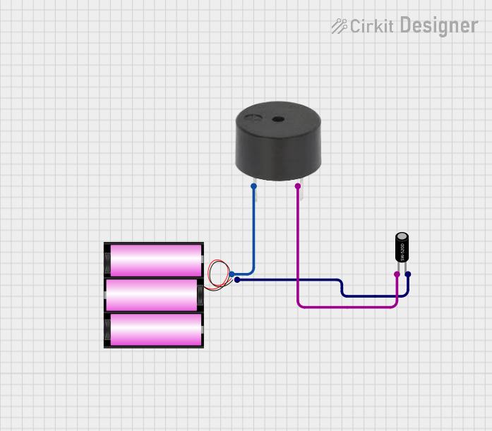
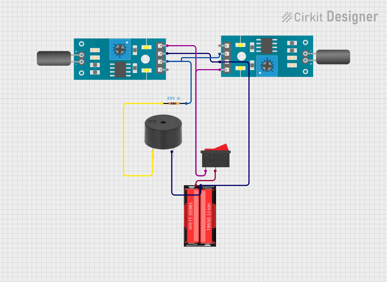
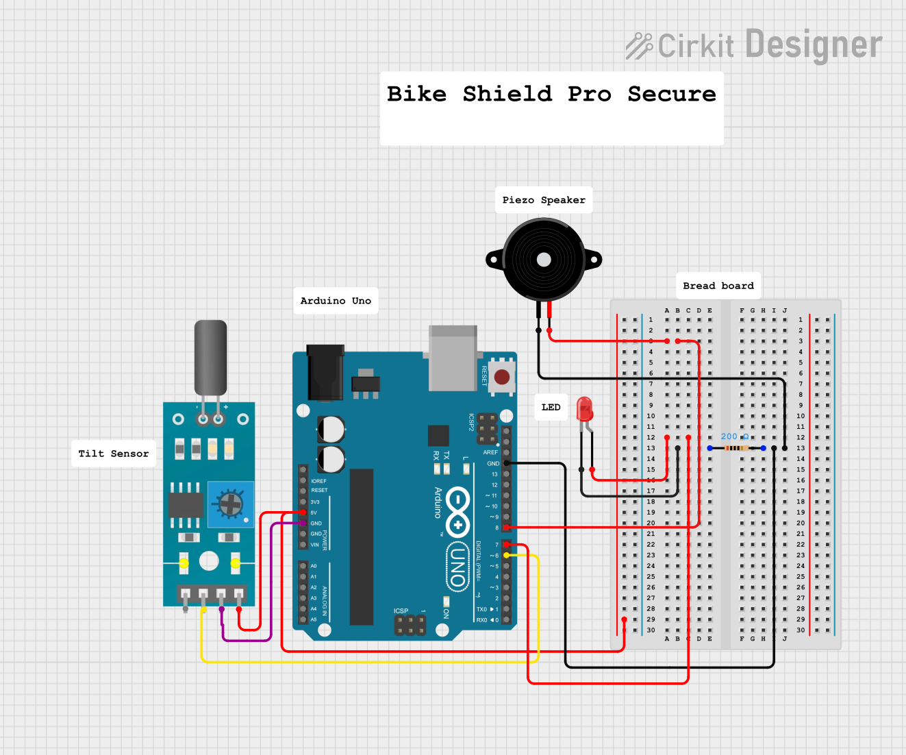
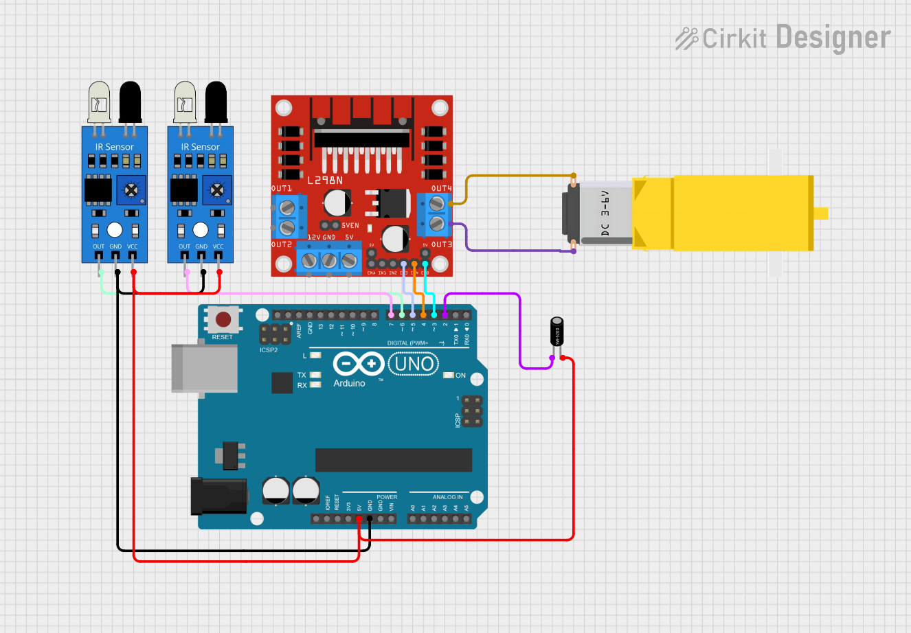
Explore Projects Built with tilt sensor
Common Applications and Use Cases
- Mobile Devices: Detecting screen orientation for portrait/landscape viewing.
- Automotive: Vehicle dynamic monitoring, such as hill start assistance.
- Security Systems: Alerting when an object is moved from its normal position.
- Consumer Electronics: Game controllers to detect motion and orientation.
- Industrial Applications: Monitoring the angle of machinery and equipment.
Technical Specifications
Key Technical Details
- Operating Voltage Range: Typically 3.3V to 5V.
- Current Consumption: Varies with model, often in the microamp range.
- Output Type: Digital (on/off) or analog (varying voltage).
- Tilt Detection Range: 0° to 180°, model-specific.
- Operating Temperature Range: Usually -25°C to +85°C.
Pin Configuration and Descriptions
| Pin Number | Description | Notes |
|---|---|---|
| 1 | GND (Ground) | Connect to system ground. |
| 2 | VCC (Power Supply) | Connect to 3.3V or 5V supply. |
| 3 | SIG (Signal Output) | Outputs the tilt status signal. |
Usage Instructions
How to Use the Component in a Circuit
Power Connection: Connect the VCC pin to a 3.3V or 5V power supply from your circuit, and the GND pin to the common ground.
Signal Output: Connect the SIG pin to a digital input pin on your microcontroller if it's a digital tilt sensor, or to an analog input if it's an analog model.
Mounting: Ensure the tilt sensor is mounted securely to the object whose tilt is being measured. Orientation of the sensor will affect its sensitivity to tilt.
Important Considerations and Best Practices
- Debounce: Tilt sensors may require debouncing, either through software or with external circuitry, to avoid false triggering from vibration or sudden movements.
- Calibration: Some sensors may need calibration to ensure accurate tilt measurements.
- Environmental Factors: Be aware of the operating temperature range and ensure the sensor is not exposed to conditions outside its specifications.
Example Code for Arduino UNO
// Define the tilt sensor pin
const int tiltSensorPin = 2;

// Variable to hold the tilt sensor status
int tiltStatus = 0;

void setup() {
  // Set the tilt sensor pin as an input
  pinMode(tiltSensorPin, INPUT);

  // Begin serial communication at 9600 baud rate
  Serial.begin(9600);
}

void loop() {
  // Read the status of the tilt sensor
  tiltStatus = digitalRead(tiltSensorPin);

  // Print the status to the serial monitor
  Serial.println(tiltStatus);

  // Delay for a bit to avoid spamming the serial monitor
  delay(100);
}
Troubleshooting and FAQs
Common Issues Users Might Face
- Inconsistent Readings: If the tilt sensor provides inconsistent readings, ensure it is mounted stably and check for any loose connections.
- No Response: Verify that the sensor is correctly powered and that the signal pin is connected to the correct input on the microcontroller.
- False Triggers: Implement debouncing in your code or add a hardware debounce circuit to filter out noise.
Solutions and Tips for Troubleshooting
- Check Connections: Double-check all wiring and solder joints for solid connections.
- Power Supply: Ensure the power supply is within the sensor's operating voltage range.
- Code Debugging: Use serial output to debug the sensor's readings and ensure the logic in your code is correct.
FAQs
Q: Can I use a tilt sensor with a 3.3V system? A: Yes, most tilt sensors can operate at 3.3V, but always check the specific model's datasheet.
Q: How do I know if my tilt sensor is analog or digital? A: Check the datasheet or product specifications. A digital sensor will have a binary output (on/off), while an analog sensor will provide a range of values corresponding to the angle of tilt.
Q: What is the purpose of debouncing a tilt sensor? A: Debouncing is used to eliminate false triggers caused by noise or rapid movement that can cause the sensor to switch states erratically.
Q: Can tilt sensors detect rotation? A: Tilt sensors are designed to detect inclination, not rotation. For rotational detection, a gyroscope or a rotary encoder would be more appropriate.
Remember to always refer to the specific datasheet of the tilt sensor model you are using for the most accurate and detailed information.