How to Use Arduino Mega & ESP8266: Examples, Pinouts, and Specs
Introduction
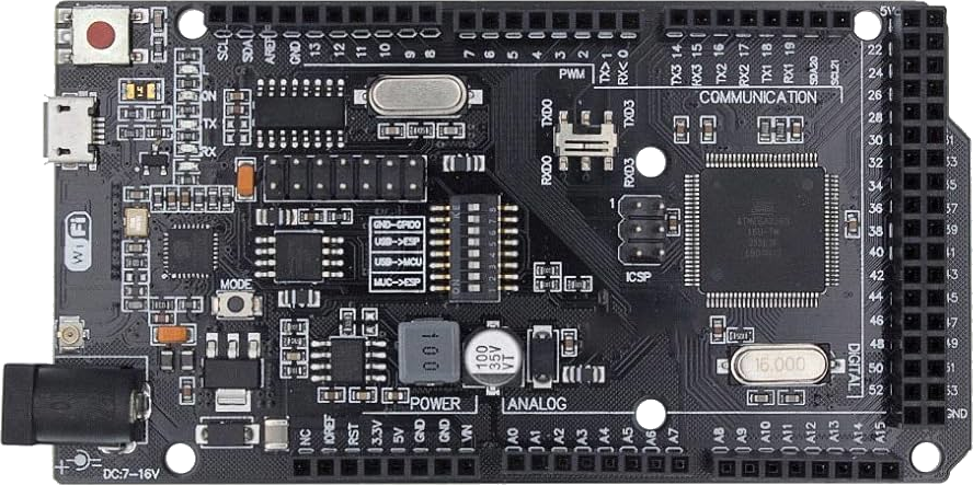
The Arduino Mega is a microcontroller board based on the ATmega2560, designed for projects requiring a large number of input/output pins and memory. The ESP8266 is a low-cost Wi-Fi module that enables wireless communication for IoT (Internet of Things) applications. When combined, the Arduino Mega and ESP8266 provide a powerful platform for creating connected devices with extensive I/O capabilities and wireless networking.
Explore Projects Built with Arduino Mega & ESP8266
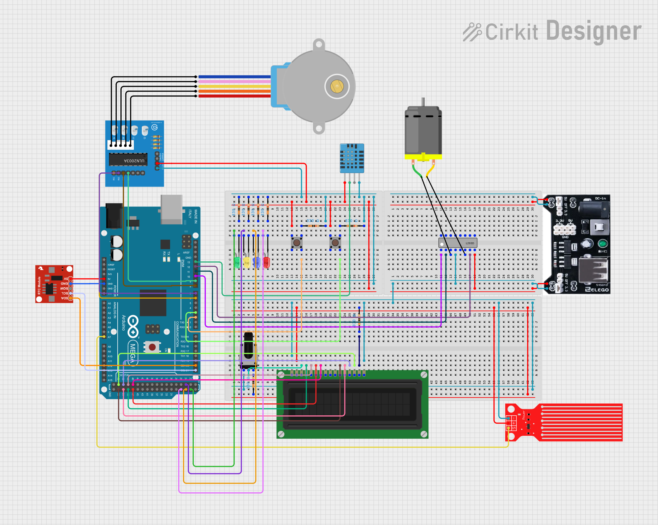
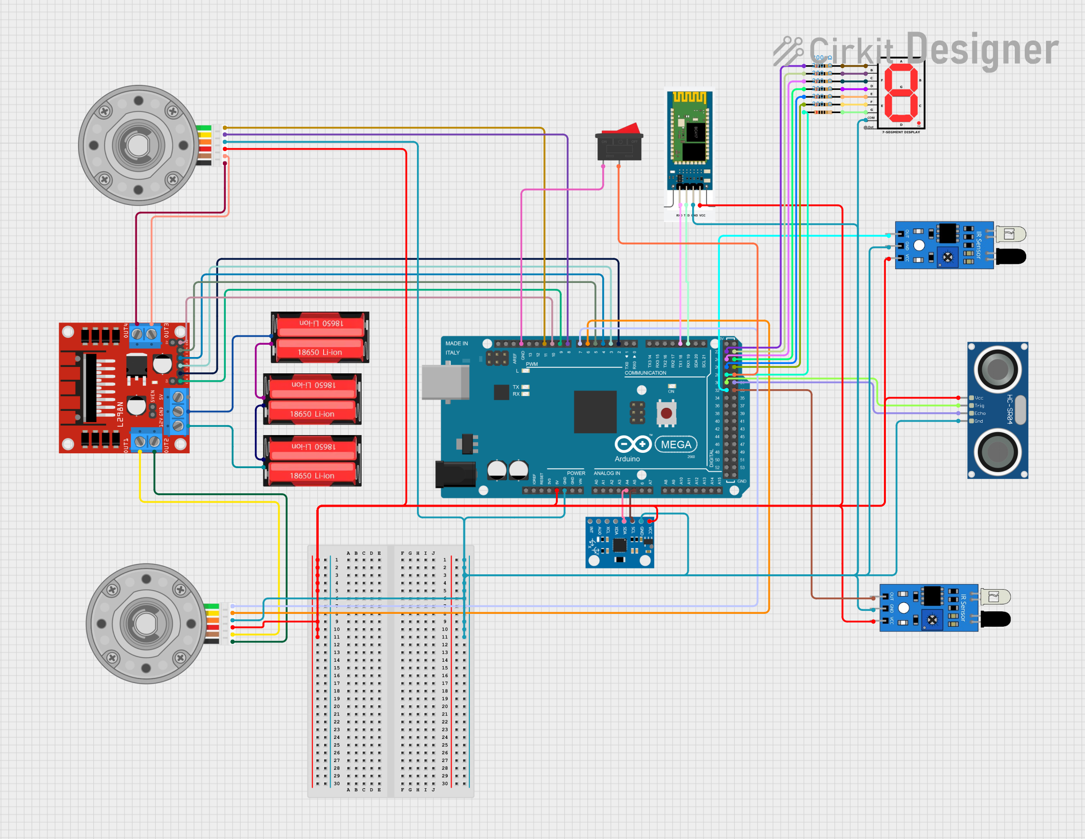
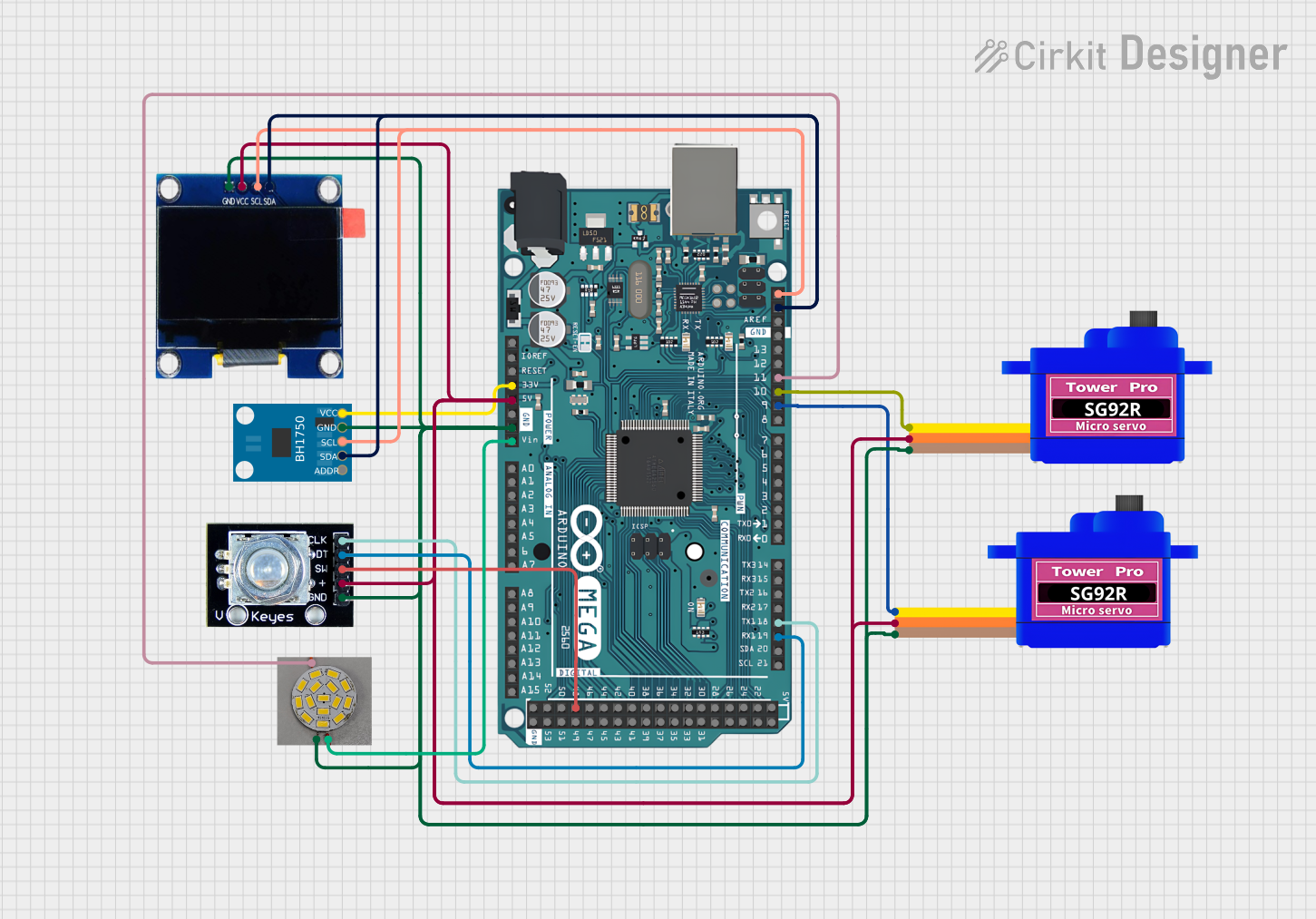
Explore Projects Built with Arduino Mega & ESP8266
Common Applications and Use Cases
- Home automation systems
- IoT devices and prototypes
- Wireless sensor networks
- Remote data logging and monitoring
- Smart appliances and robotics
Technical Specifications
Arduino Mega Specifications
| Parameter | Value |
|---|---|
| Microcontroller | ATmega2560 |
| Operating Voltage | 5V |
| Input Voltage (limits) | 6-20V |
| Digital I/O Pins | 54 (15 PWM outputs) |
| Analog Input Pins | 16 |
| Flash Memory | 256 KB (8 KB used by bootloader) |
| SRAM | 8 KB |
| EEPROM | 4 KB |
| Clock Speed | 16 MHz |
ESP8266 Specifications
| Parameter | Value |
|---|---|
| Microcontroller | Tensilica L106 32-bit RISC |
| Operating Voltage | 3.3V |
| Wi-Fi Standards | 802.11 b/g/n |
| Flash Memory | 1 MB to 16 MB (varies by model) |
| GPIO Pins | Up to 17 |
| Clock Speed | 80 MHz (default) or 160 MHz |
| Communication Protocols | UART, SPI, I2C |
Pin Configuration for ESP8266 (ESP-01 Module)
| Pin Name | Description |
|---|---|
| VCC | Power input (3.3V) |
| GND | Ground |
| TX | UART Transmit |
| RX | UART Receive |
| CH_PD | Chip Enable (connect to 3.3V for operation) |
| GPIO0 | General Purpose I/O (used for boot mode selection) |
| GPIO2 | General Purpose I/O |
| RST | Reset (active low) |
Usage Instructions
Connecting Arduino Mega to ESP8266
- Power Supply: Ensure the ESP8266 is powered with 3.3V. Do not connect it directly to the 5V pin of the Arduino Mega, as it may damage the module.
- Voltage Level Shifting: Use a voltage divider or level shifter for the TX pin of the Arduino Mega to step down the 5V signal to 3.3V for the ESP8266 RX pin.
- Wiring:
- Connect the ESP8266
VCCto a 3.3V power source. - Connect
GNDto the common ground of the Arduino Mega. - Connect the ESP8266
TXto the Arduino MegaRX1(pin 19). - Connect the ESP8266
RXto the Arduino MegaTX1(pin 18) through a voltage divider or level shifter. - Connect
CH_PDto 3.3V to enable the ESP8266.
- Connect the ESP8266
Sample Code for Arduino Mega with ESP8266
The following code demonstrates how to send AT commands to the ESP8266 and establish a Wi-Fi connection.
#include <SoftwareSerial.h>

// Define RX and TX pins for ESP8266 communication
SoftwareSerial espSerial(18, 19); // RX = pin 18, TX = pin 19

void setup() {
  // Initialize serial communication for debugging
  Serial.begin(9600);
  while (!Serial) {
    ; // Wait for the serial port to connect
  }
  Serial.println("Serial communication started.");

  // Initialize ESP8266 communication
  espSerial.begin(115200); // Default baud rate for ESP8266
  Serial.println("ESP8266 communication initialized.");

  // Send AT command to test communication
  sendATCommand("AT");
}

void loop() {
  // Check for data from ESP8266
  if (espSerial.available()) {
    String response = espSerial.readString();
    Serial.println("ESP8266 Response: " + response);
  }

  // Check for user input from Serial Monitor
  if (Serial.available()) {
    String command = Serial.readString();
    sendATCommand(command);
  }
}

// Function to send AT commands to ESP8266
void sendATCommand(String command) {
  espSerial.println(command); // Send command to ESP8266
  Serial.println("Command sent: " + command); // Debug output
}
Important Considerations
- Power Supply: Use a stable 3.3V power source for the ESP8266. Avoid powering it directly from the Arduino Mega's 3.3V pin if the current demand exceeds its capacity.
- Baud Rate: Ensure the baud rate of the ESP8266 matches the configuration in your code. The default is often 115200 but can be changed using AT commands.
- Common Ground: Always connect the ground of the Arduino Mega and ESP8266 to ensure proper communication.
Troubleshooting and FAQs
Common Issues
ESP8266 Not Responding to AT Commands
- Cause: Incorrect wiring or baud rate mismatch.
- Solution: Double-check the connections and ensure the baud rate in the code matches the ESP8266's default baud rate.
ESP8266 Keeps Resetting
- Cause: Insufficient power supply.
- Solution: Use a dedicated 3.3V power source capable of supplying at least 300mA.
Garbage Data in Serial Monitor
- Cause: Baud rate mismatch between the Serial Monitor and ESP8266.
- Solution: Set the Serial Monitor baud rate to match the ESP8266's baud rate.
Wi-Fi Connection Fails
- Cause: Incorrect SSID or password.
- Solution: Verify the Wi-Fi credentials and ensure the router is within range.
FAQs
Can I use the Arduino Mega's 5V pin to power the ESP8266? No, the ESP8266 operates at 3.3V and may be damaged by 5V. Use a 3.3V regulator or a dedicated power supply.
How do I change the ESP8266's baud rate? Use the AT command
AT+UART_DEF=<baud>,8,1,0,0to set the desired baud rate. For example,AT+UART_DEF=9600,8,1,0,0sets the baud rate to 9600.Can I use the Arduino Mega's hardware serial ports for the ESP8266? Yes, the Arduino Mega has multiple hardware serial ports (Serial1, Serial2, Serial3) that can be used for communication with the ESP8266.
By following this documentation, you can successfully integrate the Arduino Mega and ESP8266 for your IoT projects.