Cirkit Designer
Your all-in-one circuit design IDE
Home /
Component Documentation
How to Use buck converter: Examples, Pinouts, and Specs
Introduction
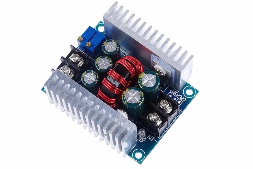
A buck converter, also known as a step-down converter, is an essential electronic component used to convert a higher direct current (DC) input voltage to a lower DC output voltage using a switching regulator. The MASS 12345 model is designed for high efficiency and reliability in a variety of applications, including but not limited to power supplies, battery chargers, and energy harvesting systems.
Explore Projects Built with buck converter
Multi-Stage Voltage Regulation and Indicator LED Circuit

This circuit is designed for power management, featuring buck and boost converters for voltage adjustment, and linear regulators for stable voltage output. It includes LEDs for status indication, and terminal blocks for external connections.
Dual Motor Control Circuit with Directional Switching and Voltage Regulation

This circuit features a 12V battery connected through a rocker switch to two buck converters, one of which steps down the voltage to power two DC mini metal gear motors, and the other is connected to a directional switch that controls a third DC mini metal gear motor. The XL4015 5A DC Buck Step-down converter's output is connected to two motors, allowing them to run at a reduced voltage, while the other buck converter's output is routed through a directional switch to control the direction of the third motor.
Battery-Powered DC Generator with XL4015 Buck Converter

This circuit consists of a 12V battery connected to a rocker switch, which controls the input to an XL4015 DC Buck Step-down converter. The converter steps down the voltage to power a DC generator, with the generator's output connected back to the converter to form a feedback loop.
Battery-Powered UPS with Step-Down Buck Converter and BMS

This circuit is a power management system that steps down a 240V AC input to a lower DC voltage using a buck converter, which then powers a 40W UPS. The UPS is controlled by a rocker switch and is backed up by a battery management system (BMS) connected to three 3.7V batteries in series, ensuring continuous power supply.
Explore Projects Built with buck converter
Multi-Stage Voltage Regulation and Indicator LED Circuit
This circuit is designed for power management, featuring buck and boost converters for voltage adjustment, and linear regulators for stable voltage output. It includes LEDs for status indication, and terminal blocks for external connections.
Dual Motor Control Circuit with Directional Switching and Voltage Regulation
This circuit features a 12V battery connected through a rocker switch to two buck converters, one of which steps down the voltage to power two DC mini metal gear motors, and the other is connected to a directional switch that controls a third DC mini metal gear motor. The XL4015 5A DC Buck Step-down converter's output is connected to two motors, allowing them to run at a reduced voltage, while the other buck converter's output is routed through a directional switch to control the direction of the third motor.
Battery-Powered DC Generator with XL4015 Buck Converter
This circuit consists of a 12V battery connected to a rocker switch, which controls the input to an XL4015 DC Buck Step-down converter. The converter steps down the voltage to power a DC generator, with the generator's output connected back to the converter to form a feedback loop.
Battery-Powered UPS with Step-Down Buck Converter and BMS
This circuit is a power management system that steps down a 240V AC input to a lower DC voltage using a buck converter, which then powers a 40W UPS. The UPS is controlled by a rocker switch and is backed up by a battery management system (BMS) connected to three 3.7V batteries in series, ensuring continuous power supply.
Common Applications and Use Cases
- Power Management: Regulating voltage in portable devices to extend battery life.
- Automotive Electronics: Powering sensors and microcontrollers at lower voltages.
- Industrial Systems: Providing stable voltage in automation and control equipment.
- Consumer Electronics: Used in laptops, smartphones, and other personal gadgets.
Technical Specifications
Key Technical Details
- Input Voltage Range: 4.5V to 20V
- Output Voltage Range: 1.0V to 15V
- Maximum Output Current: 3A
- Switching Frequency: 500 kHz
- Efficiency: Up to 95%
- Operating Temperature: -40°C to +85°C
Pin Configuration and Descriptions
| Pin Number | Name | Description |
|---|---|---|
| 1 | VIN | Input voltage supply pin. Connect to the source voltage. |
| 2 | GND | Ground pin. Connect to the system ground. |
| 3 | VOUT | Output voltage pin. Connect to the load. |
| 4 | SW | Switch pin. Connects to the internal switch. |
| 5 | FB | Feedback pin. Used for output voltage regulation. |
| 6 | EN | Enable pin. Logic high enables the converter, low disables it. |
| 7 | SS | Soft-start pin. Controls the start-up timing. |
Usage Instructions
How to Use the Component in a Circuit
- Input Supply: Connect a DC voltage source within the specified input range to the VIN pin.
- Output Load: Connect the load to the VOUT pin.
- Grounding: Ensure the GND pin is connected to the system ground.
- Feedback Network: Attach a voltage divider from VOUT to FB to set the output voltage.
- Enable Pin: Apply a logic high signal to the EN pin to turn on the buck converter.
- Soft-Start: Optionally, connect a capacitor to the SS pin to manage the start-up rate.
Important Considerations and Best Practices
- Input Capacitor: Place a capacitor close to the VIN pin to stabilize the input supply.
- Output Capacitor: Use a capacitor at the VOUT pin to smooth the output voltage.
- Inductor Selection: Choose an inductor with an appropriate current rating and low DC resistance.
- Thermal Management: Ensure adequate cooling for the component, especially at high power levels.
- Switching Noise: Minimize noise by keeping the layout compact and using proper filtering.
Troubleshooting and FAQs
Common Issues Users Might Face
- Output Voltage Instability: Check the feedback network and ensure proper capacitor values.
- Overheating: Verify the power dissipation and improve heat sinking if necessary.
- Noise Issues: Review the layout and add filtering or shielding to reduce electromagnetic interference.
Solutions and Tips for Troubleshooting
- No Output Voltage: Ensure the EN pin is high and the input voltage is within the specified range.
- Low Efficiency: Check for excessive input or output ripple and replace capacitors if needed.
- Unexpected Shutdowns: Confirm that the current limit is not being exceeded and improve airflow.
Example Code for Arduino UNO
// Example code to control the MASS 12345 Buck Converter with an Arduino UNO

const int enablePin = 9; // Connect to the EN pin of the buck converter

void setup() {
  pinMode(enablePin, OUTPUT);
  digitalWrite(enablePin, LOW); // Start with the converter disabled
}

void loop() {
  // Enable the buck converter
  digitalWrite(enablePin, HIGH);
  delay(5000); // Wait for 5 seconds

  // Disable the buck converter
  digitalWrite(enablePin, LOW);
  delay(5000); // Wait for 5 seconds
}
Note: This code assumes that the buck converter's EN pin is connected to digital pin 9 on the Arduino UNO. The converter is toggled on and off every 5 seconds.
For further assistance or inquiries regarding the MASS 12345 Buck Converter, please contact our technical support team.