How to Use 2SC5200: Examples, Pinouts, and Specs
Introduction
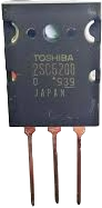
The 2SC5200 is a high-power NPN bipolar junction transistor (BJT) manufactured by Toshiba. It is widely used in audio amplifier circuits and other high-power applications due to its excellent performance characteristics, including high voltage and current handling capabilities. This transistor is designed for linear amplification and switching applications, making it a versatile choice for engineers and hobbyists alike.
Explore Projects Built with 2SC5200

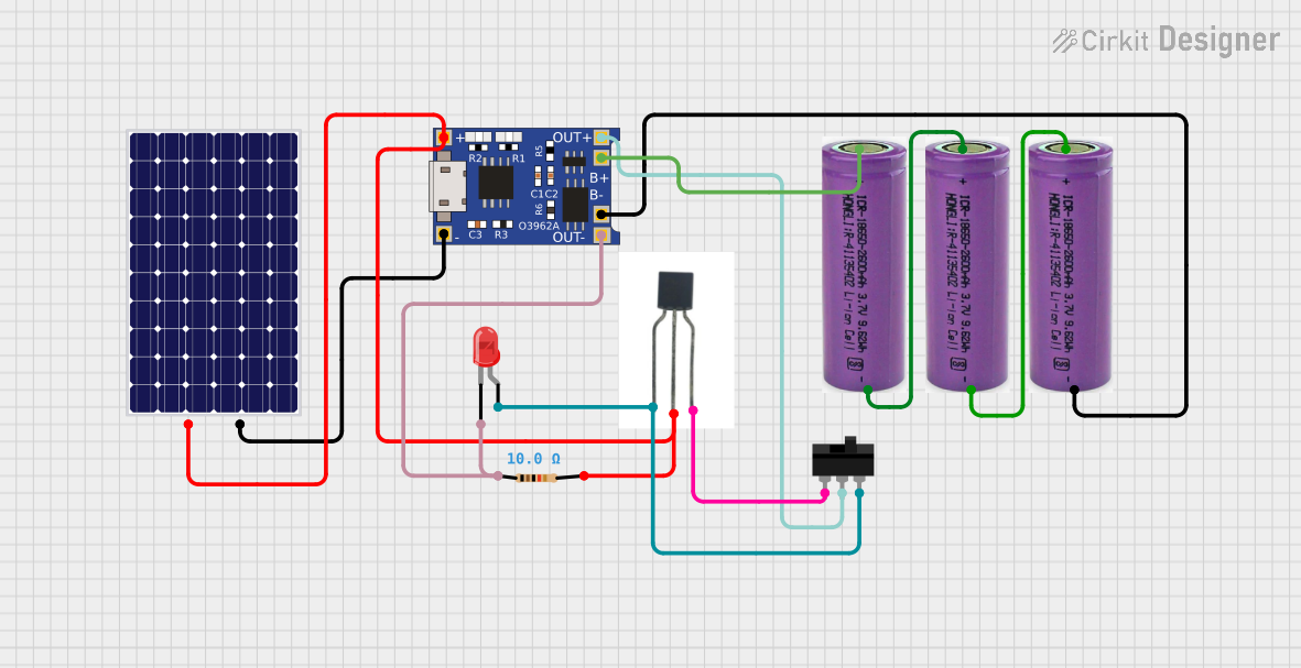
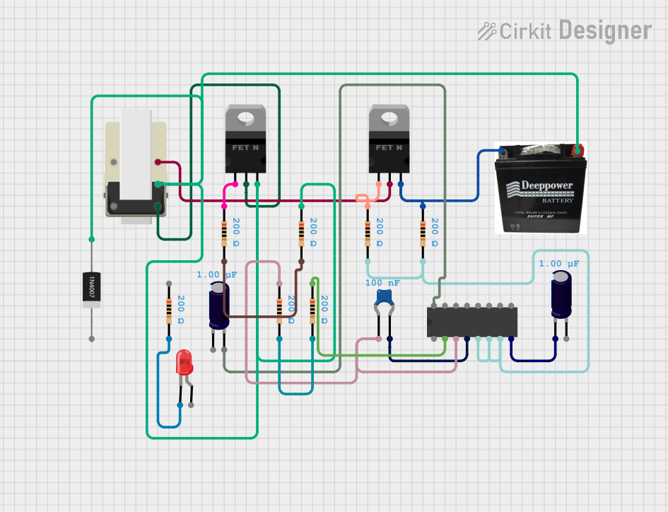

Explore Projects Built with 2SC5200
Common Applications and Use Cases
- High-power audio amplifiers
- Power supply circuits
- Motor control systems
- Switching applications in industrial equipment
- General-purpose high-power amplification
Technical Specifications
Below are the key technical details of the 2SC5200 transistor:
| Parameter | Value |
|---|---|
| Manufacturer | Toshiba |
| Part Number | 2SC5200 |
| Transistor Type | NPN |
| Maximum Collector-Emitter Voltage (Vceo) | 230V |
| Maximum Collector-Base Voltage (Vcbo) | 230V |
| Maximum Emitter-Base Voltage (Vebo) | 5V |
| Maximum Collector Current (Ic) | 15A |
| Maximum Power Dissipation (Pc) | 150W |
| DC Current Gain (hFE) | 55 to 160 |
| Transition Frequency (fT) | 30 MHz |
| Package Type | TO-264 |
| Operating Temperature Range | -55°C to +150°C |
Pin Configuration and Descriptions
The 2SC5200 is housed in a TO-264 package with three pins. The pin configuration is as follows:
| Pin Number | Pin Name | Description |
|---|---|---|
| 1 | Base (B) | Controls the transistor's operation |
| 2 | Collector (C) | Current flows into this terminal |
| 3 | Emitter (E) | Current flows out of this terminal |
Usage Instructions
How to Use the 2SC5200 in a Circuit
Biasing the Transistor:
- Connect a suitable resistor to the base pin to limit the base current. The base current should typically be 1/10th of the collector current for proper operation.
- Ensure the base-emitter voltage (Vbe) is approximately 0.7V for the transistor to turn on.
Load Connection:
- Connect the load (e.g., speaker or motor) in series with the collector pin and the power supply.
- The emitter pin should be connected to the ground or the negative terminal of the power supply.
Power Dissipation:
- Use a heatsink to manage heat dissipation, as the transistor can handle up to 150W of power. Proper thermal management is critical to prevent overheating.
Protection:
- Add a flyback diode across inductive loads (e.g., motors) to protect the transistor from voltage spikes.
- Use a fuse or current-limiting resistor to prevent excessive current through the transistor.
Example Circuit with Arduino UNO
The 2SC5200 can be used to drive a high-power load, such as a motor, controlled by an Arduino UNO. Below is an example circuit and code:
Circuit Description
- The base of the 2SC5200 is connected to a digital pin of the Arduino through a 1kΩ resistor.
- The collector is connected to one terminal of the motor, and the other terminal of the motor is connected to the positive power supply.
- The emitter is connected to the ground.
Arduino Code
// Example code to control a motor using the 2SC5200 transistor
// connected to an Arduino UNO. The motor is turned on and off
// at 1-second intervals.

const int transistorPin = 9; // Pin connected to the base of 2SC5200

void setup() {
  pinMode(transistorPin, OUTPUT); // Set the pin as an output
}

void loop() {
  digitalWrite(transistorPin, HIGH); // Turn the motor ON
  delay(1000); // Wait for 1 second
  digitalWrite(transistorPin, LOW);  // Turn the motor OFF
  delay(1000); // Wait for 1 second
}
Important Considerations and Best Practices
- Always check the maximum ratings (voltage, current, and power) to avoid damaging the transistor.
- Use a heatsink to manage heat dissipation effectively.
- Ensure proper biasing of the base pin to achieve the desired operation.
- Avoid exceeding the maximum base-emitter voltage (5V) to prevent damage.
Troubleshooting and FAQs
Common Issues and Solutions
| Issue | Possible Cause | Solution |
|---|---|---|
| Transistor overheating | Insufficient heatsink or excessive current | Use a larger heatsink or reduce the load |
| No output from the transistor | Incorrect base resistor value or no base current | Check and adjust the base resistor value |
| Load not turning off completely | Leakage current or improper biasing | Verify base-emitter voltage and connections |
| Transistor damaged during operation | Exceeded maximum ratings | Ensure voltage, current, and power are within limits |
FAQs
Can the 2SC5200 be used for switching applications?
- Yes, the 2SC5200 is suitable for both linear amplification and switching applications.
What is the recommended base resistor value?
- The base resistor value depends on the desired base current. For a collector current of 10A, a base current of 1A is recommended. Use Ohm's law to calculate the resistor value: ( R = \frac{V_{in} - V_{be}}{I_b} ).
How do I protect the transistor from voltage spikes?
- Use a flyback diode across inductive loads to suppress voltage spikes and protect the transistor.
By following this documentation, you can effectively use the 2SC5200 transistor in your projects and troubleshoot common issues.