
How to Use Amica NodeMCU DEVKIT 1.0: Examples, Pinouts, and Specs
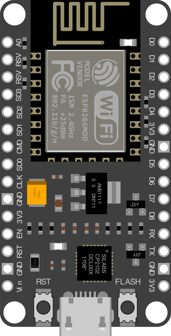
 Design with Amica NodeMCU DEVKIT 1.0 in Cirkit Designer
Introduction
The Amica NodeMCU DEVKIT 1.0 is a low-cost, open-source IoT platform based on the ESP8266 Wi-Fi module. It is designed for rapid prototyping and development of IoT applications. The board features a built-in USB interface for easy programming and debugging, as well as a variety of GPIO pins for connecting sensors, actuators, and other peripherals. Its compact design and integrated Wi-Fi capabilities make it an ideal choice for IoT projects.
Explore Projects Built with Amica NodeMCU DEVKIT 1.0
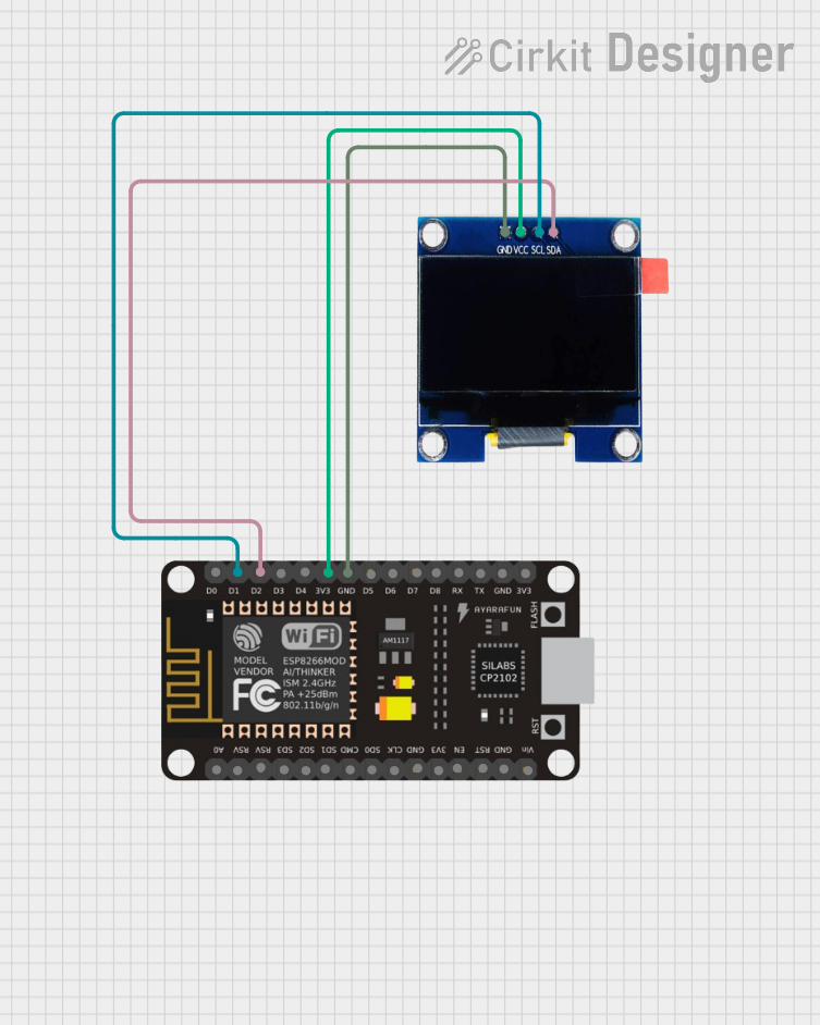 Open Project in Cirkit Designer
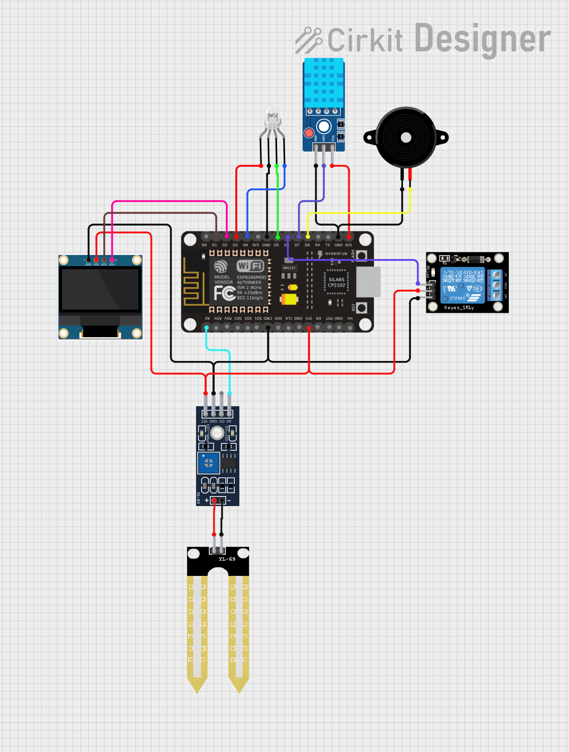 Open Project in Cirkit Designer
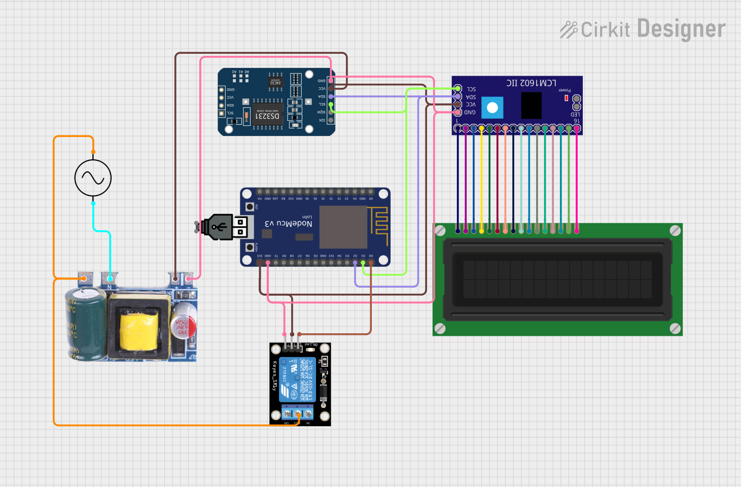 Open Project in Cirkit Designer
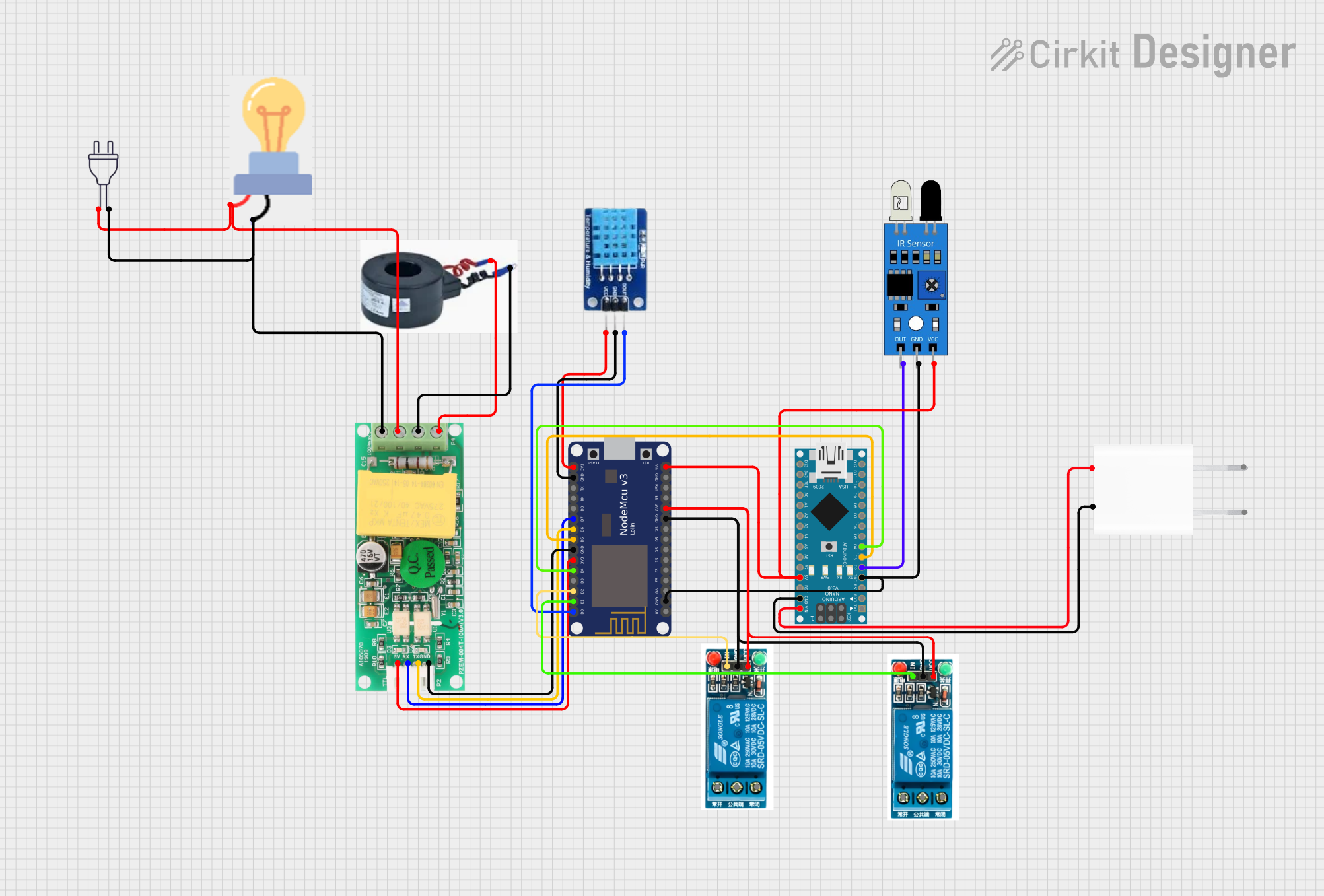 Open Project in Cirkit Designer
Explore Projects Built with Amica NodeMCU DEVKIT 1.0
Open Project in Cirkit DesignerOpen Project in Cirkit DesignerOpen Project in Cirkit DesignerOpen Project in Cirkit DesignerCommon Applications and Use Cases
- Home automation systems
- Smart lighting control
- Environmental monitoring (e.g., temperature, humidity sensors)
- IoT-enabled appliances
- Wireless data logging
- Prototyping and educational projects
Technical Specifications
Key Technical Details
| Parameter | Specification |
|---|---|
| Microcontroller | ESP8266 (Tensilica L106 32-bit RISC) |
| Operating Voltage | 3.3V |
| Input Voltage (USB) | 5V |
| Flash Memory | 4MB |
| Clock Speed | 80 MHz (up to 160 MHz) |
| GPIO Pins | 11 (including ADC) |
| ADC Resolution | 10-bit |
| Wi-Fi Standard | 802.11 b/g/n |
| USB Interface | Micro-USB |
| Dimensions | 49mm x 26mm |
Pin Configuration and Descriptions
The Amica NodeMCU DEVKIT 1.0 features a total of 30 pins, including GPIO, power, and communication pins. Below is a detailed pinout description:
| Pin Name | Pin Number | Description |
|---|---|---|
| VIN | 1 | Input voltage (5V from USB or external) |
| GND | 2, 15 | Ground |
| 3V3 | 3 | 3.3V output from onboard regulator |
| D0 | 4 | GPIO16 |
| D1 | 5 | GPIO5 (I2C SCL) |
| D2 | 6 | GPIO4 (I2C SDA) |
| D3 | 7 | GPIO0 |
| D4 | 8 | GPIO2 (built-in LED) |
| D5 | 9 | GPIO14 (SPI SCLK) |
| D6 | 10 | GPIO12 (SPI MISO) |
| D7 | 11 | GPIO13 (SPI MOSI) |
| D8 | 12 | GPIO15 (SPI CS) |
| RX | 13 | UART RX (GPIO3) |
| TX | 14 | UART TX (GPIO1) |
| A0 | 16 | Analog input (0-1V) |
Usage Instructions
How to Use the Component in a Circuit
Powering the Board:
- Connect the board to your computer using a Micro-USB cable. This provides both power and a programming interface.
- Alternatively, supply 5V to the VIN pin and connect GND to the ground of your power source.
Programming the Board:
- Install the Arduino IDE and add the ESP8266 board package via the Boards Manager.
- Select "NodeMCU 1.0 (ESP-12E Module)" as the board in the Arduino IDE.
- Connect the board to your computer and select the appropriate COM port.
Connecting Peripherals:
- Use the GPIO pins to connect sensors, actuators, or other devices. Ensure that the peripherals operate at 3.3V logic levels to avoid damaging the board.
Uploading Code:
- Write your code in the Arduino IDE and click the "Upload" button to flash it to the board.
Important Considerations and Best Practices
- Voltage Levels: The GPIO pins operate at 3.3V. Avoid applying 5V directly to the pins.
- Analog Input: The A0 pin accepts a maximum voltage of 1V. Use a voltage divider if your sensor outputs higher voltages.
- Wi-Fi Configuration: Ensure your Wi-Fi credentials are correctly set in your code to avoid connection issues.
- Power Supply: If using external power, ensure it is stable and within the recommended range (5V to VIN).
Example Code for Arduino IDE
Below is an example code to connect the NodeMCU to a Wi-Fi network and blink the onboard LED:
#include <ESP8266WiFi.h>

// Replace with your network credentials
const char* ssid = "Your_SSID";
const char* password = "Your_PASSWORD";

void setup() {
  // Initialize serial communication for debugging
  Serial.begin(115200);

  // Initialize the onboard LED pin as output
  pinMode(LED_BUILTIN, OUTPUT);

  // Connect to Wi-Fi
  Serial.print("Connecting to Wi-Fi");
  WiFi.begin(ssid, password);

  while (WiFi.status() != WL_CONNECTED) {
    delay(500);
    Serial.print(".");
  }

  Serial.println("\nWi-Fi connected!");
  Serial.print("IP Address: ");
  Serial.println(WiFi.localIP());
}

void loop() {
  // Blink the onboard LED
  digitalWrite(LED_BUILTIN, LOW); // Turn LED on
  delay(1000);                   // Wait for 1 second
  digitalWrite(LED_BUILTIN, HIGH); // Turn LED off
  delay(1000);                   // Wait for 1 second
}
Troubleshooting and FAQs
Common Issues and Solutions
Board Not Detected by Computer:
- Ensure the USB cable is functional and supports data transfer.
- Install the appropriate USB-to-serial driver (e.g., CH340 or CP2102).
Upload Fails with "esptool.FatalError":
- Check that the correct COM port is selected in the Arduino IDE.
- Ensure the board is in programming mode by pressing the "Flash" button during upload.
Wi-Fi Connection Issues:
- Verify that the SSID and password in your code are correct.
- Ensure the Wi-Fi network is within range and not using unsupported security protocols.
GPIO Pin Not Responding:
- Confirm that the pin is not being used for another function (e.g., UART, SPI).
- Check for wiring issues or incorrect logic levels.
FAQs
Q: Can I power the NodeMCU with a battery?
A: Yes, you can use a 3.7V LiPo battery connected to the VIN and GND pins. Ensure the battery voltage is regulated to 5V for stable operation.
Q: What is the maximum current the GPIO pins can source/sink?
A: Each GPIO pin can source/sink up to 12mA. For higher currents, use an external transistor or relay.
Q: Can I use the NodeMCU with MicroPython?
A: Yes, the NodeMCU supports MicroPython. You can flash the MicroPython firmware to the board and use Python for programming.
Q: How do I reset the board?
A: Press the "RST" button on the board to perform a hardware reset.