
How to Use SOIC18-W: Examples, Pinouts, and Specs
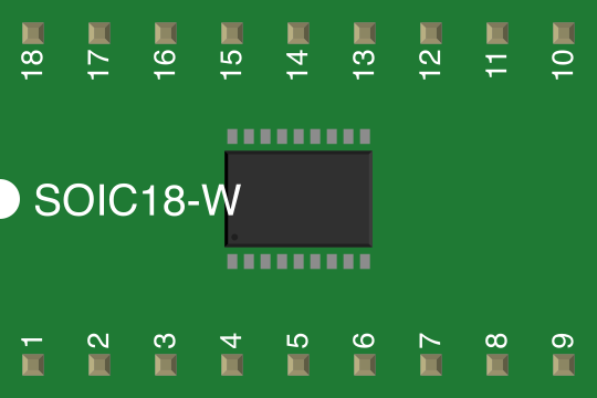
 Design with SOIC18-W in Cirkit Designer
Introduction
The SOIC18-W is a small outline integrated circuit (SOIC) package with 18 pins, designed for surface mounting on printed circuit boards (PCBs). Its compact footprint and wide body design make it ideal for applications where space-saving and reliability are critical. The SOIC18-W package is widely used in consumer electronics, automotive systems, industrial controls, and communication devices. It is compatible with automated assembly processes, making it a popular choice for high-volume manufacturing.
Explore Projects Built with SOIC18-W
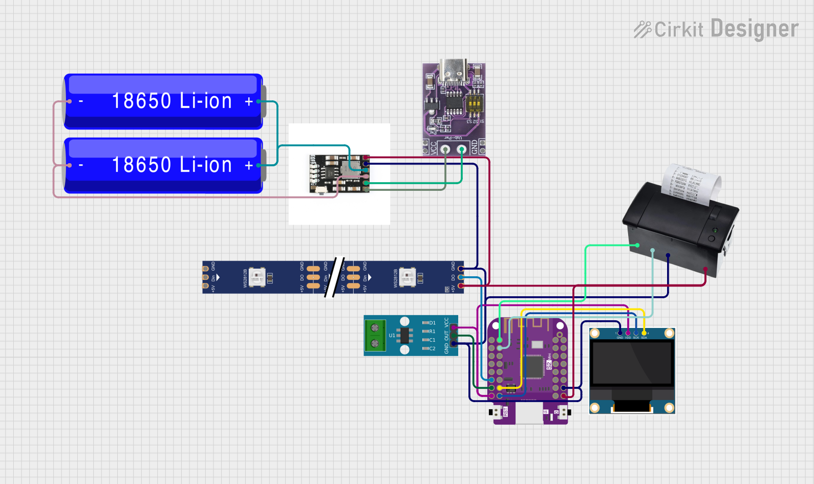 Open Project in Cirkit Designer
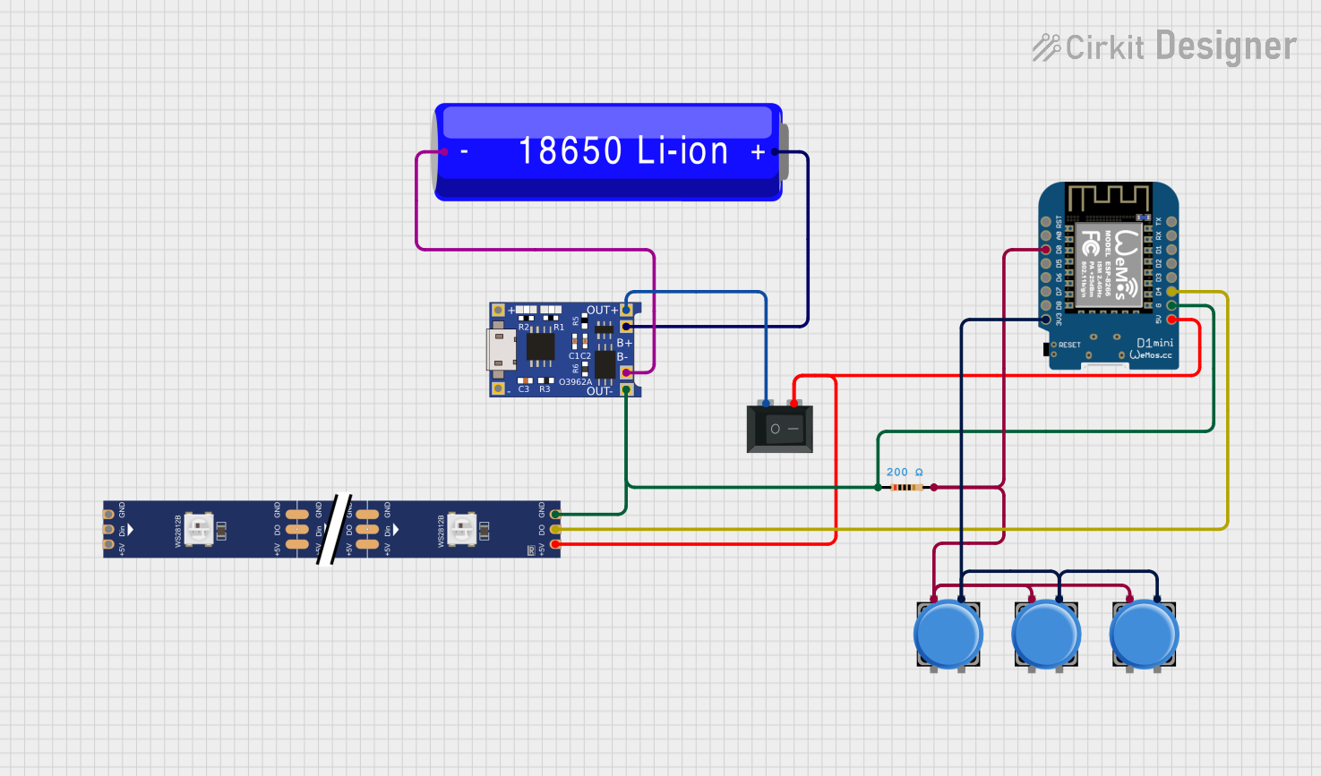 Open Project in Cirkit Designer
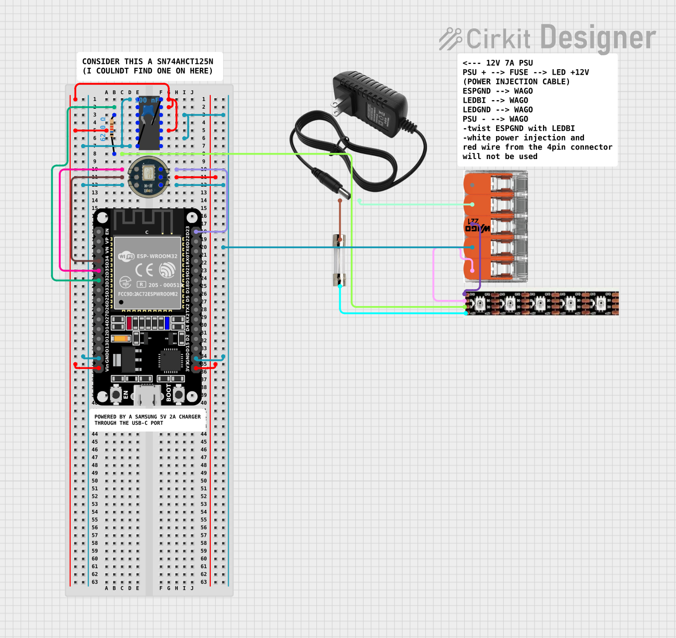 Open Project in Cirkit Designer
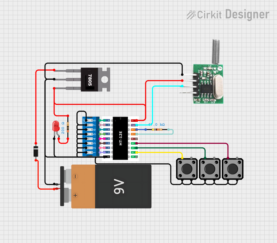 Open Project in Cirkit Designer
Explore Projects Built with SOIC18-W
Open Project in Cirkit DesignerOpen Project in Cirkit DesignerOpen Project in Cirkit DesignerOpen Project in Cirkit DesignerCommon Applications
- Microcontrollers and digital ICs
- Analog-to-digital converters (ADCs) and digital-to-analog converters (DACs)
- Memory ICs (e.g., EEPROM, Flash)
- Power management ICs
- Signal processing and communication modules
Technical Specifications
Key Technical Details
| Parameter | Specification |
|---|---|
| Package Type | SOIC (Small Outline Integrated Circuit) |
| Pin Count | 18 |
| Body Width | 7.5 mm (Wide Body) |
| Pin Pitch | 1.27 mm |
| Maximum Height | 2.65 mm |
| Operating Temperature | -40°C to +125°C |
| Mounting Type | Surface Mount (SMT) |
| Lead Finish | Matte Tin or Lead-Free Options |
Pin Configuration and Descriptions
The SOIC18-W package has 18 pins arranged in two parallel rows. The pin configuration and descriptions depend on the specific IC housed in the package. Below is a generic example for an 18-pin microcontroller:
| Pin Number | Pin Name | Description |
|---|---|---|
| 1 | VCC | Power supply (positive voltage input) |
| 2 | GND | Ground (0V reference) |
| 3 | GPIO1 | General-purpose input/output pin |
| 4 | GPIO2 | General-purpose input/output pin |
| 5 | TX | UART Transmit |
| 6 | RX | UART Receive |
| 7 | PWM1 | Pulse-width modulation output |
| 8 | PWM2 | Pulse-width modulation output |
| 9 | ADC_IN1 | Analog-to-digital converter input 1 |
| 10 | ADC_IN2 | Analog-to-digital converter input 2 |
| 11 | SPI_MOSI | SPI Master Out Slave In |
| 12 | SPI_MISO | SPI Master In Slave Out |
| 13 | SPI_SCK | SPI Clock |
| 14 | SPI_CS | SPI Chip Select |
| 15 | I2C_SDA | I2C Data Line |
| 16 | I2C_SCL | I2C Clock Line |
| 17 | RESET | Reset input |
| 18 | INT | Interrupt input |
Note: The actual pinout may vary depending on the specific IC housed in the SOIC18-W package. Always refer to the datasheet of the specific IC for accurate pin descriptions.
Usage Instructions
How to Use the SOIC18-W in a Circuit
- PCB Design: Ensure the PCB layout matches the SOIC18-W footprint. The pin pitch is 1.27 mm, and the body width is 7.5 mm. Use solder mask openings and thermal relief pads for optimal soldering.
- Soldering: Use surface-mount technology (SMT) for soldering. Reflow soldering is recommended for automated assembly.
- Power Supply: Connect the VCC and GND pins to the appropriate power supply. Ensure the voltage and current ratings match the IC specifications.
- Signal Connections: Connect the signal pins (e.g., GPIO, UART, SPI, I2C) to the corresponding components in your circuit.
- Bypass Capacitors: Place decoupling capacitors (e.g., 0.1 µF) close to the VCC pin to filter out noise and stabilize the power supply.
Important Considerations and Best Practices
- Thermal Management: Ensure adequate heat dissipation, especially for high-power ICs. Use thermal vias and copper planes if necessary.
- ESD Protection: Handle the SOIC18-W package with care to avoid electrostatic discharge (ESD) damage. Use ESD-safe tools and workstations.
- Pin Alignment: Verify the orientation of the IC before soldering. The pin 1 indicator (dot or notch) should align with the PCB layout.
Example: Connecting an SOIC18-W Microcontroller to Arduino UNO
If the SOIC18-W package houses a microcontroller, you can interface it with an Arduino UNO using UART communication. Below is an example Arduino code to send data to the microcontroller:
// Example: Sending data to an SOIC18-W microcontroller via UART
// Connect the TX pin of the Arduino to the RX pin of the SOIC18-W microcontroller
// Connect the RX pin of the Arduino to the TX pin of the SOIC18-W microcontroller

void setup() {
  Serial.begin(9600); // Initialize UART communication at 9600 baud rate
  delay(1000);        // Wait for the microcontroller to initialize
}

void loop() {
  Serial.println("Hello, SOIC18-W!"); // Send a message to the microcontroller
  delay(1000);                       // Wait for 1 second before sending again
}
Note: Ensure the voltage levels of the Arduino and the SOIC18-W microcontroller are compatible. Use a level shifter if necessary.
Troubleshooting and FAQs
Common Issues
- Incorrect Pin Alignment: If the IC does not function, check the orientation and ensure pin 1 is correctly aligned with the PCB layout.
- Soldering Defects: Cold solder joints or solder bridges can cause connectivity issues. Inspect the soldering under a microscope.
- Power Supply Problems: If the IC does not power on, verify the voltage and current supplied to the VCC and GND pins.
- Communication Errors: For UART, SPI, or I2C communication, ensure proper wiring and matching baud rates or clock frequencies.
Solutions and Tips
- Use a multimeter to check for continuity and proper connections.
- Refer to the IC datasheet for detailed electrical characteristics and pin functions.
- If the IC overheats, check for short circuits or excessive current draw.
FAQs
Q: Can I hand-solder the SOIC18-W package?
A: Yes, but it requires precision. Use a fine-tipped soldering iron and flux to avoid solder bridges.
Q: What is the difference between SOIC18-W and SOIC18-N?
A: The "W" indicates a wide body (7.5 mm), while "N" typically refers to a narrow body (3.9 mm).
Q: How do I clean the PCB after soldering?
A: Use isopropyl alcohol and a soft brush to remove flux residues.
Q: Can I use the SOIC18-W package for prototyping?
A: Yes, but you may need an SOIC-to-DIP adapter for breadboard compatibility.
By following this documentation, you can effectively integrate the SOIC18-W package into your electronic designs. Always consult the specific IC datasheet for additional details and recommendations.