How to Use 2.9" Greyscale eInk: Examples, Pinouts, and Specs
Introduction
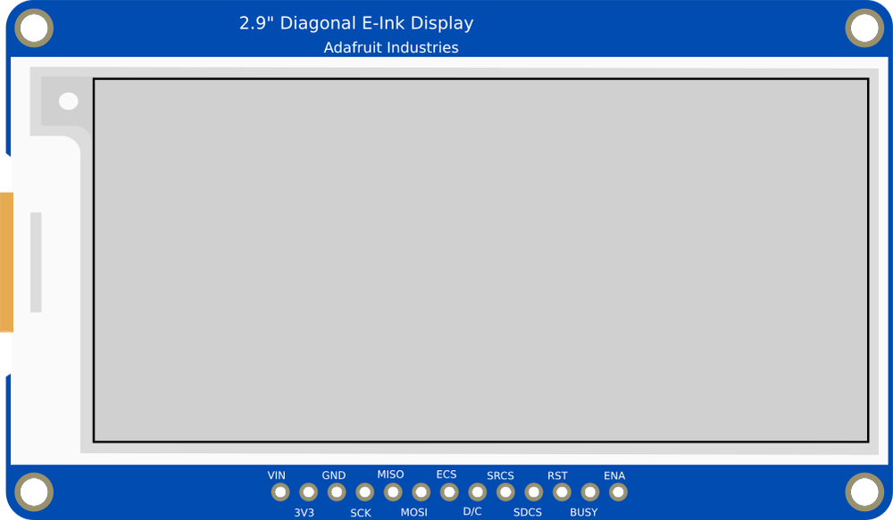
The Adafruit 2.9" eInk Display (Manufacturer Part ID: Adafruit 2.9" eInk) is a 2.9-inch greyscale electronic paper display that utilizes eInk technology. This display is designed to provide high-contrast, low-power visual output, making it ideal for applications where static images or text need to be displayed for extended periods without consuming power. Unlike traditional displays, eInk technology mimics the appearance of ink on paper, offering excellent readability even in bright sunlight.
Explore Projects Built with 2.9" Greyscale eInk

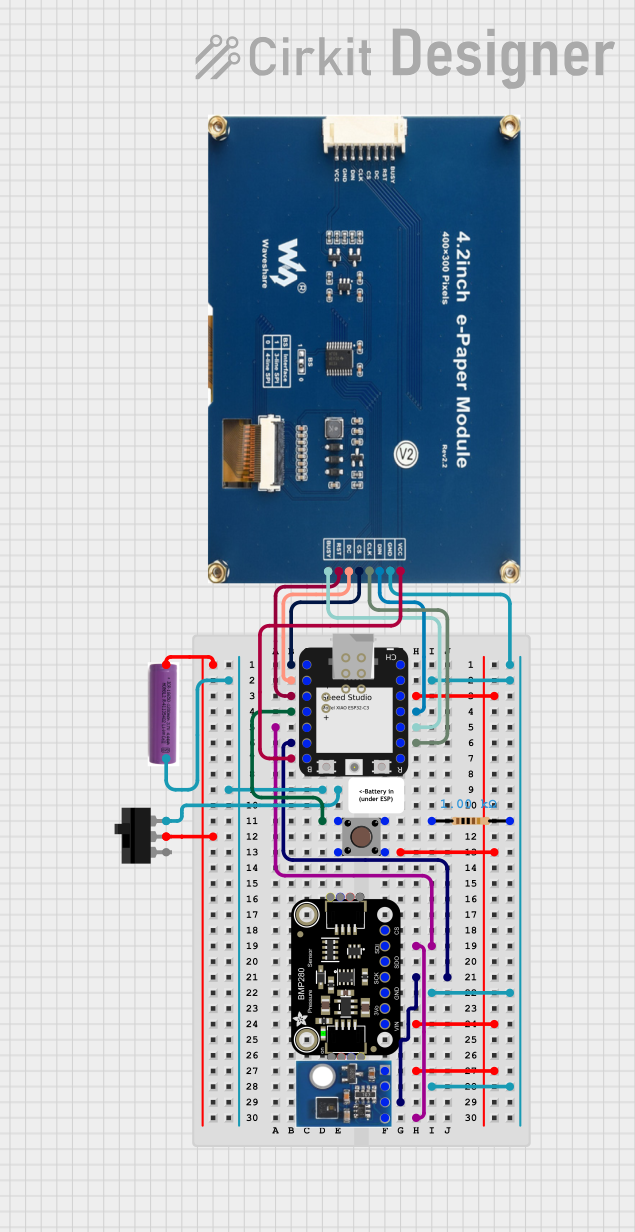
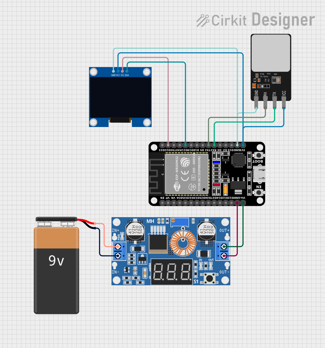
Explore Projects Built with 2.9" Greyscale eInk
Common Applications and Use Cases
- eBook readers: Displays text and images with paper-like clarity.
- Digital signage: Ideal for price tags, shelf labels, and other static displays.
- IoT devices: Displays sensor data or status updates with minimal power consumption.
- Wearables: Used in smartwatches or badges for low-power, always-on displays.
- Prototyping: Perfect for hobbyists and developers working on low-power display projects.
Technical Specifications
Below are the key technical details for the Adafruit 2.9" eInk display:
| Specification | Details |
|---|---|
| Display Type | eInk (Electronic Paper Display) |
| Display Size | 2.9 inches diagonal |
| Resolution | 296 x 128 pixels |
| Color Depth | 3 colors (Black, White, and Red or Yellow, depending on the variant) |
| Interface | SPI (Serial Peripheral Interface) |
| Operating Voltage | 3.3V logic |
| Power Consumption | Ultra-low power (only consumes power during updates) |
| Refresh Time | ~2 seconds (varies depending on the image complexity) |
| Viewing Angle | Nearly 180° |
| Dimensions | 79mm x 36.7mm x 1.18mm |
| Weight | ~10g |
Pin Configuration and Descriptions
The Adafruit 2.9" eInk display uses an SPI interface for communication. Below is the pinout:
| Pin Name | Pin Number | Description |
|---|---|---|
| VCC | 1 | Power supply input (3.3V). |
| GND | 2 | Ground connection. |
| DIN | 3 | SPI data input (MOSI - Master Out Slave In). |
| CLK | 4 | SPI clock input (SCK). |
| CS | 5 | Chip select (active low). |
| DC | 6 | Data/Command control pin. |
| RST | 7 | Reset pin (active low). |
| BUSY | 8 | Busy status pin (indicates when the display is updating). |
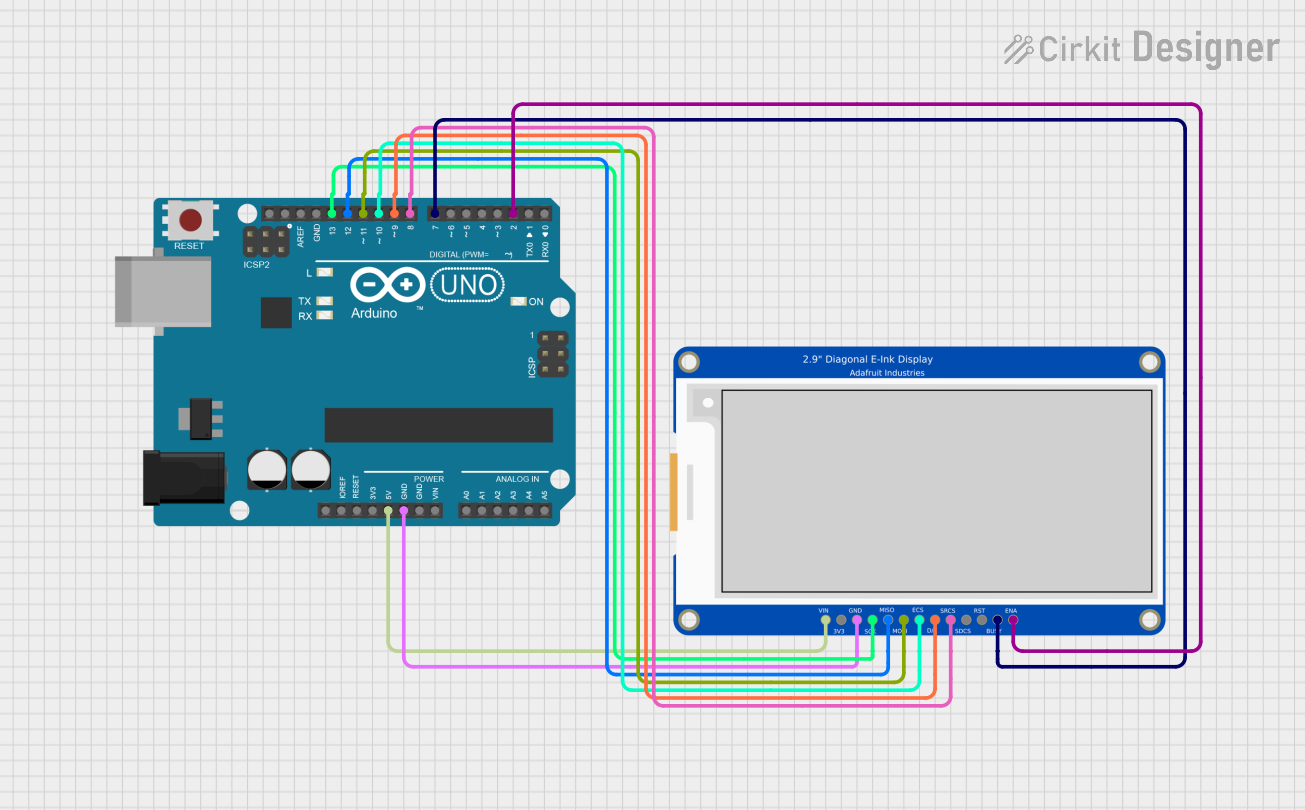
Usage Instructions
How to Use the Component in a Circuit
- Power Supply: Connect the VCC pin to a 3.3V power source and the GND pin to ground.
- SPI Communication: Connect the SPI pins (DIN, CLK, CS) to the corresponding SPI pins on your microcontroller.
- Control Pins:
- Connect the DC pin to a GPIO pin on your microcontroller to toggle between data and command modes.
- Connect the RST pin to a GPIO pin to reset the display when needed.
- Connect the BUSY pin to a GPIO pin to monitor the display's status.
- Library and Driver: Use the Adafruit GFX and Adafruit EPD libraries to control the display. These libraries provide functions for drawing text, shapes, and images.
Important Considerations and Best Practices
- Power Consumption: The display only consumes power during updates. Ensure your circuit design accounts for this.
- Refresh Time: The display refresh is not instantaneous (~2 seconds). Avoid frequent updates to maximize efficiency.
- Handling: Avoid bending or applying pressure to the display, as eInk panels are fragile.
- Logic Level: Ensure your microcontroller operates at 3.3V logic levels. If using a 5V microcontroller, use a level shifter.
Example Code for Arduino UNO
Below is an example of how to use the Adafruit 2.9" eInk display with an Arduino UNO:
#include <Adafruit_GFX.h>    // Core graphics library
#include <Adafruit_EPD.h>    // eInk display library

// Pin definitions for the eInk display
#define EPD_CS   10  // Chip select pin
#define EPD_DC    9  // Data/Command pin
#define EPD_RST   8  // Reset pin
#define EPD_BUSY  7  // Busy pin

// Create an instance of the display class
Adafruit_IL0373 display(296, 128, EPD_CS, EPD_DC, EPD_RST, EPD_BUSY);

void setup() {
  // Initialize serial communication for debugging
  Serial.begin(9600);
  Serial.println("Initializing eInk display...");

  // Initialize the display
  display.begin();

  // Clear the display
  display.clearBuffer();

  // Draw text on the display
  display.setTextSize(2);  // Set text size
  display.setTextColor(EPD_BLACK);  // Set text color
  display.setCursor(10, 10);  // Set cursor position
  display.println("Hello, eInk!");

  // Draw a rectangle
  display.drawRect(5, 5, 100, 50, EPD_BLACK);

  // Update the display to show the changes
  display.display();
}

void loop() {
  // The display does not need to be refreshed in the loop unless content changes
}
Notes:
- Install the Adafruit GFX and Adafruit EPD libraries via the Arduino Library Manager before running the code.
- Ensure the pin connections match the pin definitions in the code.
Troubleshooting and FAQs
Common Issues and Solutions
Display Not Turning On:
- Verify the power supply is 3.3V and properly connected to the VCC and GND pins.
- Check all SPI connections for loose or incorrect wiring.
No Output on the Display:
- Ensure the Adafruit GFX and Adafruit EPD libraries are installed and up to date.
- Verify the pin definitions in the code match your wiring.
Display Stuck in Busy State:
- Check the BUSY pin connection.
- Ensure the microcontroller is not sending commands while the display is updating.
Partial or Corrupted Display Updates:
- Ensure the SPI clock speed is within the display's supported range.
- Avoid interrupting the display update process.
FAQs
Can I use this display with a 5V microcontroller?
- Yes, but you must use a logic level shifter to convert 5V signals to 3.3V.
How long does the display retain an image without power?
- The display can retain an image indefinitely without power, as long as it is not physically disturbed.
Can I display images on this eInk display?
- Yes, you can display monochrome or 3-color images using the Adafruit EPD library.
What is the lifespan of the display?
- The display is rated for thousands of updates, making it suitable for long-term use in most applications.