How to Use Kaki MY2N: Examples, Pinouts, and Specs
Introduction
The Kaki MY2N is an electromechanical relay manufactured by SMKN 2 Trenggalek. It is designed for switching applications, allowing low-power control signals to manage high-power loads. With its compact design and reliable performance, the Kaki MY2N is widely used in automation, industrial control systems, and home appliances. It is available in coil voltage variants of 12V or 24V, making it versatile for various circuit designs.
Explore Projects Built with Kaki MY2N
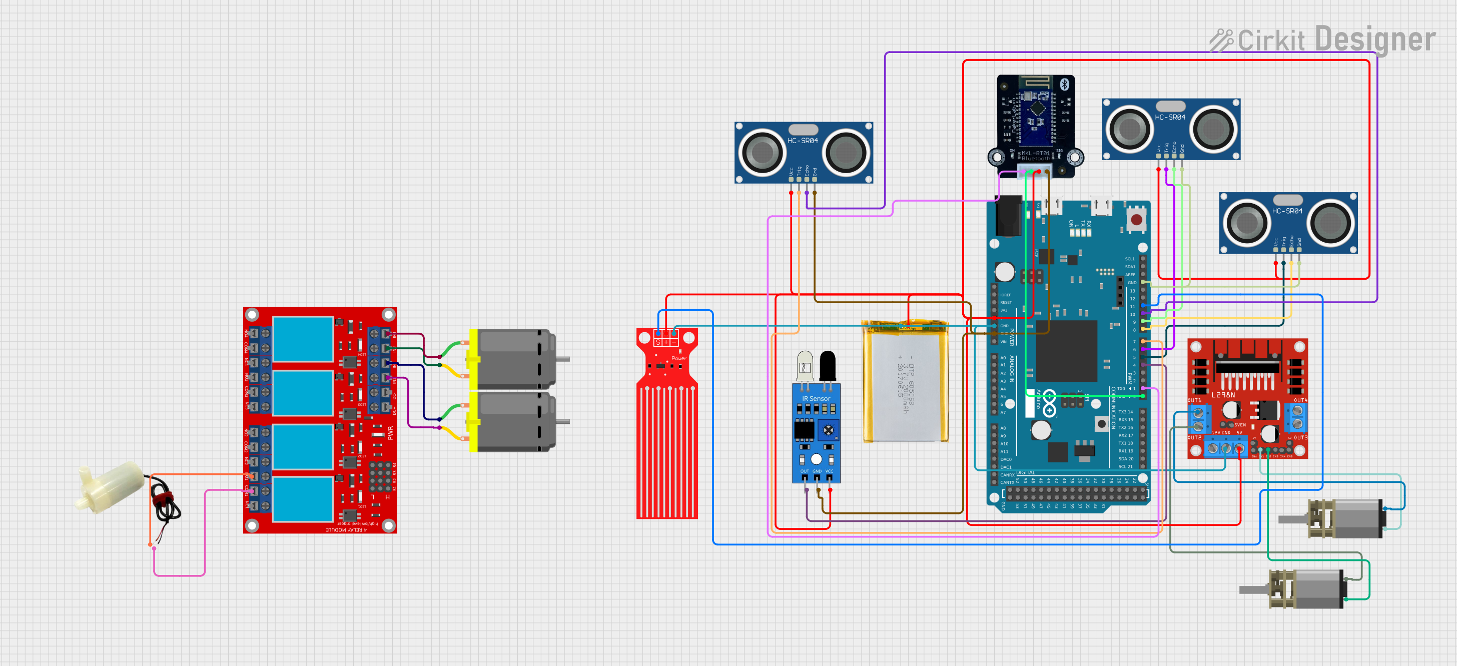
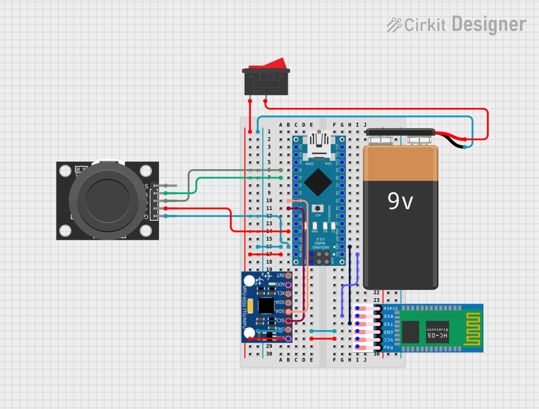


Explore Projects Built with Kaki MY2N
Common Applications
- Industrial automation systems
- Motor control circuits
- Home appliance control
- Signal switching in control panels
- Power distribution systems
Technical Specifications
Key Specifications
| Parameter | Value |
|---|---|
| Manufacturer | SMKN 2 Trenggalek |
| Part ID | SMKN 2 Trenggalek |
| Coil Voltage | 12V DC or 24V DC |
| Contact Configuration | DPDT (Double Pole Double Throw) |
| Contact Rating | 5A at 250V AC / 30V DC |
| Coil Resistance | 400Ω (12V version) / 1600Ω (24V version) |
| Operating Temperature | -40°C to +70°C |
| Insulation Resistance | ≥ 100MΩ at 500V DC |
| Dielectric Strength | 1500V AC for 1 minute |
| Dimensions | 28mm x 21mm x 36mm |
| Weight | Approximately 35g |
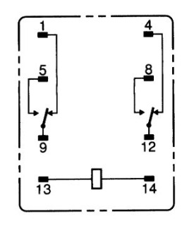
Pin Configuration
The Kaki MY2N relay has 8 pins, which are configured as follows:
| Pin Number | Description |
|---|---|
| 1 | Coil Terminal 1 (Positive) |
| 2 | Coil Terminal 2 (Negative) |
| 3 | Common Contact 1 (COM1) |
| 4 | Normally Open Contact 1 (NO1) |
| 5 | Normally Closed Contact 1 (NC1) |
| 6 | Common Contact 2 (COM2) |
| 7 | Normally Open Contact 2 (NO2) |
| 8 | Normally Closed Contact 2 (NC2) |
Usage Instructions
How to Use the Kaki MY2N in a Circuit
- Power the Coil: Connect the coil terminals (pins 1 and 2) to a DC power source matching the relay's rated coil voltage (12V or 24V). Ensure correct polarity.
- Connect the Load:
- For switching, connect the load to the common (COM) and normally open (NO) or normally closed (NC) contacts, depending on the desired operation.
- When the relay is inactive, the NC contact is connected to COM. When the relay is energized, the NO contact connects to COM.
- Control Signal: Use a low-power control signal (e.g., from a microcontroller or switch) to activate the relay coil.
Important Considerations
- Diode Protection: Place a flyback diode across the coil terminals to protect the circuit from voltage spikes when the relay is de-energized.
- Contact Ratings: Ensure the load current and voltage do not exceed the relay's contact ratings (5A at 250V AC or 30V DC).
- Mounting: Secure the relay in a socket or PCB to prevent mechanical stress.
- Isolation: Use optocouplers or transistors to isolate the control circuit from the relay coil if necessary.
Example: Connecting to an Arduino UNO
Below is an example of how to control the Kaki MY2N relay using an Arduino UNO:
// Define the relay control pin
const int relayPin = 7; // Connect this pin to the relay's coil terminal 1

void setup() {
  pinMode(relayPin, OUTPUT); // Set the relay pin as an output
  digitalWrite(relayPin, LOW); // Ensure the relay is off initially
}

void loop() {
  // Turn the relay on
  digitalWrite(relayPin, HIGH);
  delay(1000); // Keep the relay on for 1 second

  // Turn the relay off
  digitalWrite(relayPin, LOW);
  delay(1000); // Keep the relay off for 1 second
}
Note: Use a transistor or relay driver circuit to interface the Arduino with the relay, as the Arduino's GPIO pins cannot directly supply sufficient current to the relay coil.
Troubleshooting and FAQs
Common Issues and Solutions
Relay Not Activating
- Cause: Insufficient coil voltage or incorrect polarity.
- Solution: Verify the power supply voltage matches the relay's rated coil voltage. Check the polarity of the connections.
Chattering or Unstable Operation
- Cause: Insufficient current or noisy control signal.
- Solution: Ensure the power supply can provide adequate current. Use a capacitor to filter noise in the control signal.
Contacts Not Switching Properly
- Cause: Overloaded contacts or damaged relay.
- Solution: Ensure the load does not exceed the relay's contact ratings. Replace the relay if damaged.
Voltage Spikes in the Circuit
- Cause: Inductive kickback from the relay coil.
- Solution: Install a flyback diode across the coil terminals.
FAQs
Q1: Can the Kaki MY2N relay switch DC loads?
A1: Yes, the relay can switch DC loads up to 30V at 5A. Ensure the load does not exceed these ratings.
Q2: Is the relay suitable for high-frequency switching?
A2: No, the Kaki MY2N is not designed for high-frequency switching. It is best suited for low-frequency applications.
Q3: Can I use the relay with a 5V control signal?
A3: No, the relay requires a 12V or 24V coil voltage. Use a transistor or relay driver circuit to interface a 5V control signal with the relay.
Q4: How do I test if the relay is working?
A4: Apply the rated coil voltage to the coil terminals and listen for a clicking sound, which indicates the relay is switching. You can also measure continuity between the COM and NO/NC contacts.