
How to Use 12mm Trimmer Potentiometer (Large): Examples, Pinouts, and Specs

 Design with 12mm Trimmer Potentiometer (Large) in Cirkit Designer
Introduction
The 12mm Trimmer Potentiometer (Large) is a variable resistor designed for fine-tuning and calibration in electronic circuits. Its compact design makes it ideal for applications where precise voltage or current adjustments are required. This component is commonly used in devices such as amplifiers, sensors, and power supplies to adjust signal levels or calibrate circuit performance.
Explore Projects Built with 12mm Trimmer Potentiometer (Large)
 Open Project in Cirkit Designer
 Open Project in Cirkit Designer
 Open Project in Cirkit Designer
 Open Project in Cirkit Designer
Explore Projects Built with 12mm Trimmer Potentiometer (Large)
Open Project in Cirkit DesignerOpen Project in Cirkit DesignerOpen Project in Cirkit DesignerOpen Project in Cirkit DesignerCommon Applications:
- Calibration of analog circuits
- Adjusting voltage dividers
- Fine-tuning sensor sensitivity
- Setting reference voltages in power supplies
- Audio equipment for tone or volume control
Technical Specifications
Below are the key technical details of the 12mm Trimmer Potentiometer (Large):
| Parameter | Value |
|---|---|
| Resistance Range | 1 kΩ to 1 MΩ (varies by model) |
| Tolerance | ±10% |
| Power Rating | 0.5 W (at 70°C) |
| Maximum Voltage | 200 V DC |
| Adjustment Type | Top or side adjustment (varies) |
| Operating Temperature | -55°C to +125°C |
| Rotational Life | 200 cycles (typical) |
| Dimensions | 12 mm diameter, 5 mm height |
Pin Configuration and Descriptions
The 12mm Trimmer Potentiometer typically has three pins:
| Pin | Description |
|---|---|
| Pin 1 | One end of the resistive track |
| Pin 2 | Wiper (adjustable output voltage) |
| Pin 3 | The other end of the resistive track |
Note: The wiper (Pin 2) provides the adjustable output voltage, which varies depending on the position of the potentiometer's adjustment screw.
Usage Instructions
How to Use the Component in a Circuit
- Determine the Resistance Value: Select a trimmer potentiometer with the appropriate resistance range for your application.
- Connect the Pins:
- Connect Pin 1 to the input voltage or signal source.
- Connect Pin 3 to ground or the other end of the circuit.
- Connect Pin 2 (wiper) to the point in the circuit where the adjustable voltage or signal is required.
- Adjust the Potentiometer:
- Use a small screwdriver to turn the adjustment screw.
- Turning clockwise typically increases the resistance between Pin 2 and Pin 3, while decreasing the resistance between Pin 1 and Pin 2 (and vice versa).
Important Considerations and Best Practices
- Power Rating: Ensure the power dissipation across the potentiometer does not exceed its rated 0.5 W.
- Mechanical Stress: Avoid applying excessive force when adjusting the screw to prevent damage.
- Stability: For critical applications, consider using a locking mechanism or adhesive to secure the adjustment after calibration.
- Noise: Trimmer potentiometers may introduce noise in sensitive circuits. Use bypass capacitors if necessary.
Example: Using with an Arduino UNO
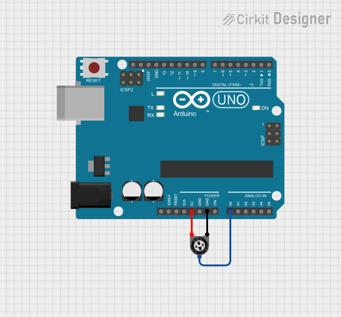
The 12mm Trimmer Potentiometer can be used to provide an adjustable input voltage to an Arduino UNO. Below is an example circuit and code:
Circuit Connections:
- Connect Pin 1 to the 5V pin on the Arduino.
- Connect Pin 3 to the GND pin on the Arduino.
- Connect Pin 2 (wiper) to an analog input pin (e.g., A0) on the Arduino.
Arduino Code:
// Example code to read the voltage from a trimmer potentiometer
// connected to analog pin A0 on an Arduino UNO.

const int potPin = A0; // Define the analog pin connected to the potentiometer
int potValue = 0;      // Variable to store the potentiometer reading

void setup() {
  Serial.begin(9600); // Initialize serial communication at 9600 baud
}

void loop() {
  potValue = analogRead(potPin); // Read the analog value from the potentiometer
  float voltage = potValue * (5.0 / 1023.0); // Convert the reading to voltage

  // Print the voltage to the Serial Monitor
  Serial.print("Potentiometer Voltage: ");
  Serial.print(voltage);
  Serial.println(" V");

  delay(500); // Wait for 500 milliseconds before the next reading
}
Note: The code reads the voltage from the potentiometer and displays it on the Serial Monitor. Adjusting the potentiometer changes the voltage output.
Troubleshooting and FAQs
Common Issues and Solutions
No Output Voltage:
- Cause: Incorrect wiring.
- Solution: Verify the connections to Pins 1, 2, and 3. Ensure the input voltage is applied to Pin 1 and Pin 3 is connected to ground.
Unstable Output:
- Cause: Loose adjustment screw or mechanical vibrations.
- Solution: Secure the adjustment screw after calibration. Use a locking mechanism if necessary.
Potentiometer Not Adjusting Properly:
- Cause: Damaged resistive track or excessive wear.
- Solution: Replace the potentiometer if it has exceeded its rotational life or shows signs of damage.
Excessive Heat:
- Cause: Power dissipation exceeds the rated 0.5 W.
- Solution: Ensure the current and voltage across the potentiometer are within its specifications.
FAQs
Q: Can I use the 12mm Trimmer Potentiometer for high-frequency signals?
A: Trimmer potentiometers are not ideal for high-frequency applications due to their inductive and capacitive parasitics. Consider using specialized components for such cases.
Q: How do I choose the correct resistance value for my application?
A: Determine the desired range of adjustment and the circuit's impedance. Select a potentiometer with a resistance value that provides sufficient adjustment range without significantly affecting the circuit's performance.
Q: Can I use this potentiometer for continuous adjustments?
A: Trimmer potentiometers are designed for occasional adjustments during calibration. For frequent adjustments, consider using a standard rotary potentiometer.
Q: What tools are recommended for adjusting the potentiometer?
A: Use a small, insulated screwdriver to avoid short circuits or damage to the component.
This concludes the documentation for the 12mm Trimmer Potentiometer (Large).