How to Use ADXL345: Examples, Pinouts, and Specs
Introduction
The ADXL345 is a compact, low-power, 3-axis accelerometer that provides high-resolution (13-bit) measurements of acceleration in up to ±16 g ranges. This MEMS sensor is designed by Analog Devices and is widely used in various applications such as mobile devices, gaming systems, personal health devices, and inertial navigation systems where tilt and motion sensing is required.
Explore Projects Built with ADXL345
Explore Projects Built with ADXL345
Common Applications and Use Cases
- Motion detection and motion processing
- Gaming and pointing devices
- Free-fall detection
- Activity monitoring
- Real-time orientation detection
- Vibration analysis and monitoring
Technical Specifications
Key Technical Details
- Power Supply: 2.0V to 3.6V
- Interface: I2C/SPI digital output interface
- Measurement Range: ±2g, ±4g, ±8g, and ±16g
- Resolution: 13-bit, 4mg/LSB
- Bandwidth: 0.1Hz to 3.2kHz
- Operating Temperature Range: -40°C to +85°C
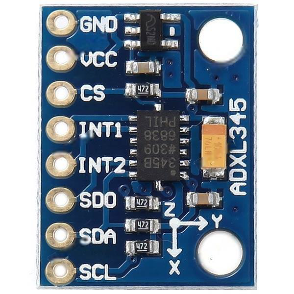
Pin Configuration and Descriptions
| Pin Number | Name | Description |
|---|---|---|
| 1 | VCC | Power supply (2.0V to 3.6V) |
| 2 | GND | Ground |
| 3 | CS | Chip select for SPI interface (active low) |
| 4 | INT1 | Interrupt output 1 |
| 5 | INT2 | Interrupt output 2 |
| 6 | SDO | Serial data output for SPI; alternate address for I2C |
| 7 | SDA | Serial data for I2C; serial data input for SPI |
| 8 | SCL | Serial clock for I2C; serial clock input for SPI |
Usage Instructions
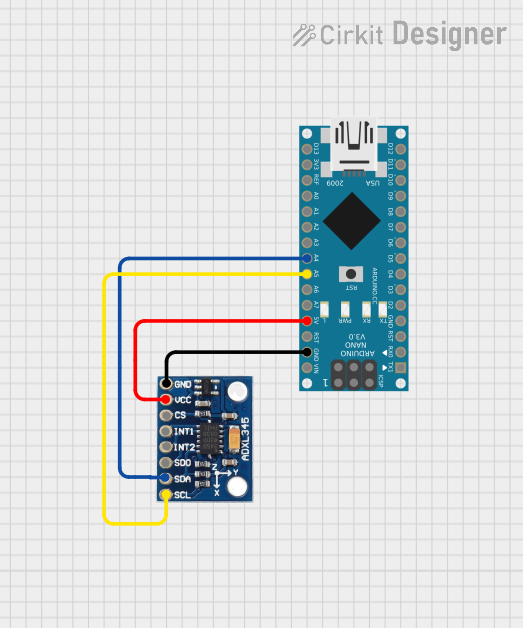
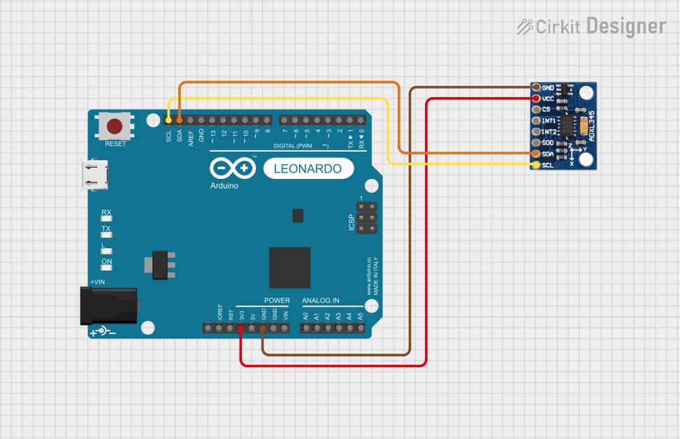
How to Use the Component in a Circuit
- Powering the Device: Connect VCC to a 2.0V to 3.6V power supply and GND to the ground.
- Selecting the Interface: Choose between I2C or SPI for communication. For I2C, connect SDA and SCL to the corresponding I2C bus lines. For SPI, connect SDA (SDI), SCL (SCK), and SDO to the SPI bus.
- Setting the Chip Select (CS): For SPI, the CS pin must be driven low to enable communication.
- Configuring Interrupts (Optional): INT1 and INT2 can be configured to output interrupt signals for events like data ready, free-fall detection, etc.
Important Considerations and Best Practices
- Ensure that the power supply voltage does not exceed 3.6V.
- Use pull-up resistors on the I2C lines if multiple devices are connected to the bus.
- Configure the device settings such as range, bandwidth, and output data rate (ODR) according to your application needs.
- Place the accelerometer as close as possible to the center of mass of the object being measured for accurate readings.
Troubleshooting and FAQs
Common Issues Users Might Face
- No Data Output: Ensure that the device is properly powered and that the I2C/SPI connections are correct. Check that the CS pin is correctly managed for SPI communication.
- Inaccurate Readings: Verify that the accelerometer is securely mounted and that there are no vibrations affecting the sensor. Calibrate the sensor if necessary.
- Communication Errors: Check for proper pull-up resistors on the I2C lines and ensure that the SPI clock speed is within the specifications.
Solutions and Tips for Troubleshooting
- Double-check wiring and solder connections.
- Use an oscilloscope or logic analyzer to verify communication signals.
- Reset the device and reconfigure it if you encounter continuous problems.
FAQs
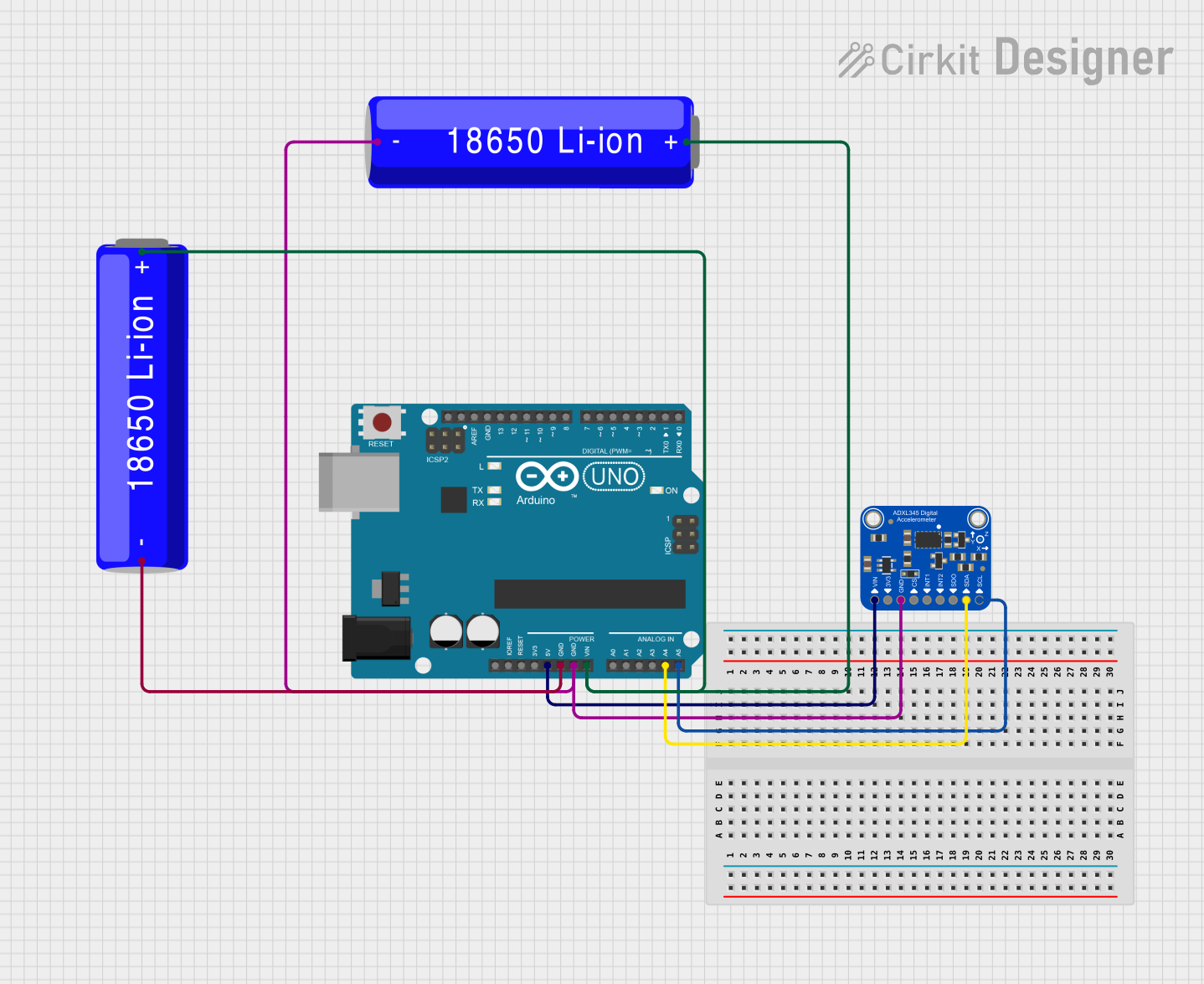
Q: Can the ADXL345 be used with an Arduino? A: Yes, the ADXL345 can be easily interfaced with an Arduino using either I2C or SPI.
Q: What is the purpose of the CS pin? A: The CS pin is used to select the ADXL345 when using SPI communication. It must be driven low to enable the device.
Q: How can I change the measurement range of the ADXL345? A: The measurement range can be changed by configuring the DATA_FORMAT register.
Q: What is the maximum sampling rate of the ADXL345? A: The maximum sampling rate (ODR) of the ADXL345 is 3200 Hz.
Example Arduino Code
Below is an example of how to interface the ADXL345 with an Arduino UNO using I2C:
#include <Wire.h>
#include <ADXL345.h>

ADXL345 accelerometer;

void setup() {
  Serial.begin(9600);
  Wire.begin(); // Initialize I2C
  if (!accelerometer.begin()) {
    Serial.println("Could not find a valid ADXL345 sensor, check wiring!");
    while (1);
  }
  // Set measurement range to ±16g
  accelerometer.setRange(ADXL345_RANGE_16_G);
}

void loop() {
  // Read the acceleration values
  sensors_event_t event;
  accelerometer.getEvent(&event);

  // Display the results (acceleration is measured in m/s^2)
  Serial.print("X: ");
  Serial.print(event.acceleration.x);
  Serial.print(" m/s^2, Y: ");
  Serial.print(event.acceleration.y);
  Serial.print(" m/s^2, Z: ");
  Serial.print(event.acceleration.z);
  Serial.println(" m/s^2");

  delay(500);
}
Note: This code assumes the use of the ADXL345 library, which provides the ADXL345 class and related methods for interacting with the sensor. Make sure to install the library through the Arduino IDE before compiling the code.