
How to Use 12V Solenoid Lock: Examples, Pinouts, and Specs
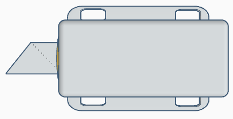
 Design with 12V Solenoid Lock in Cirkit Designer
Introduction
The 12V Solenoid Lock is an electromechanical locking device that operates by using a solenoid to control the locking mechanism. When a 12V DC voltage is applied, the solenoid activates, retracting the locking pin to unlock the mechanism. Once the voltage is removed, the spring-loaded pin returns to its locked position. This component is widely used in access control systems, vending machines, lockers, and other security applications where electronic control of locking is required.
Explore Projects Built with 12V Solenoid Lock
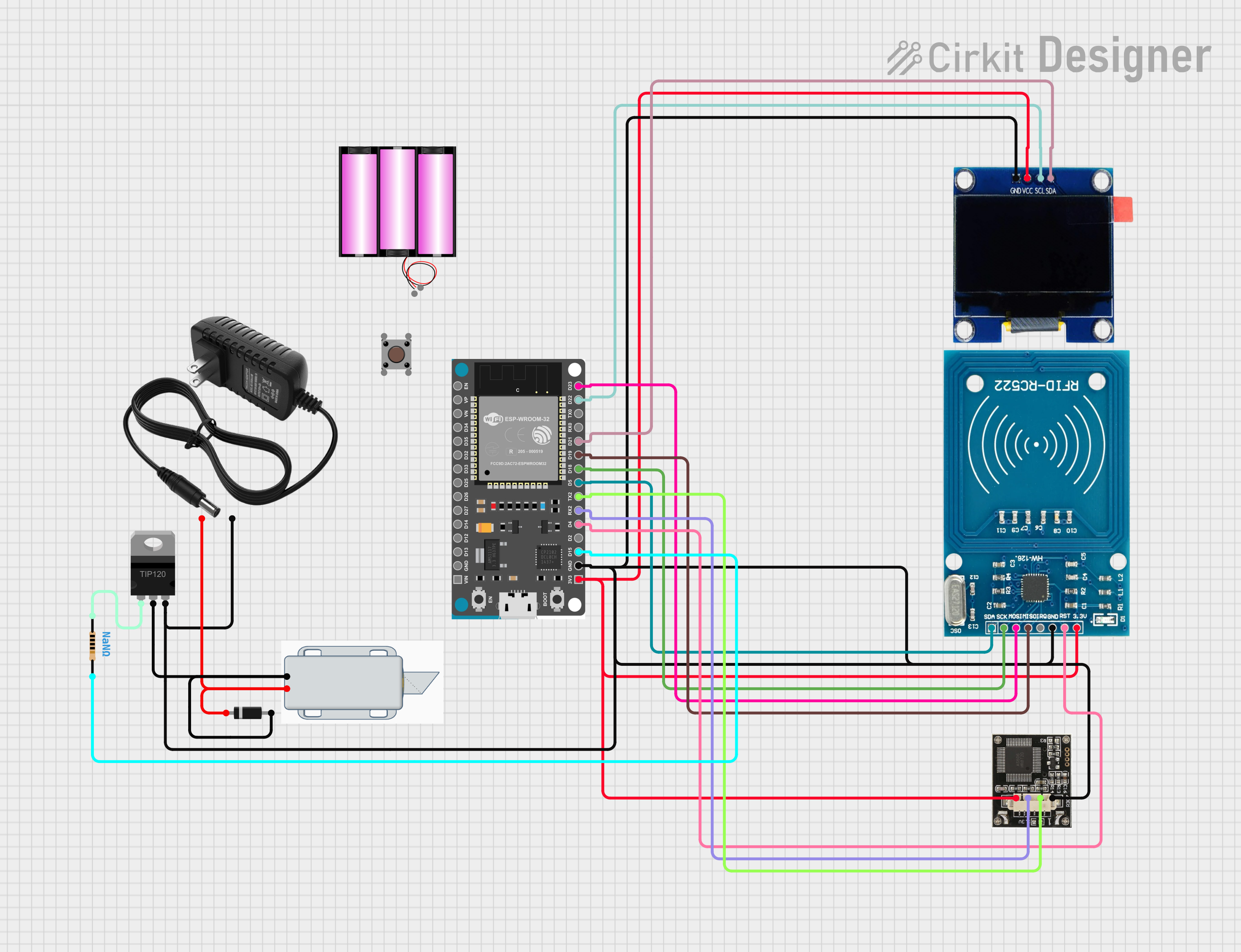 Open Project in Cirkit Designer
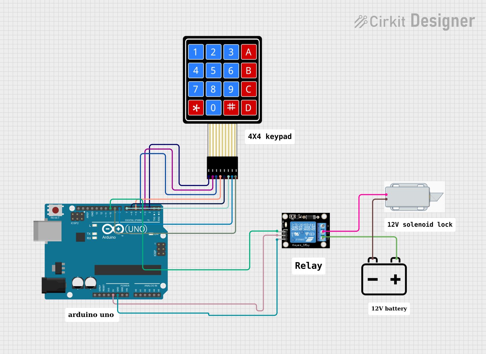 Open Project in Cirkit Designer
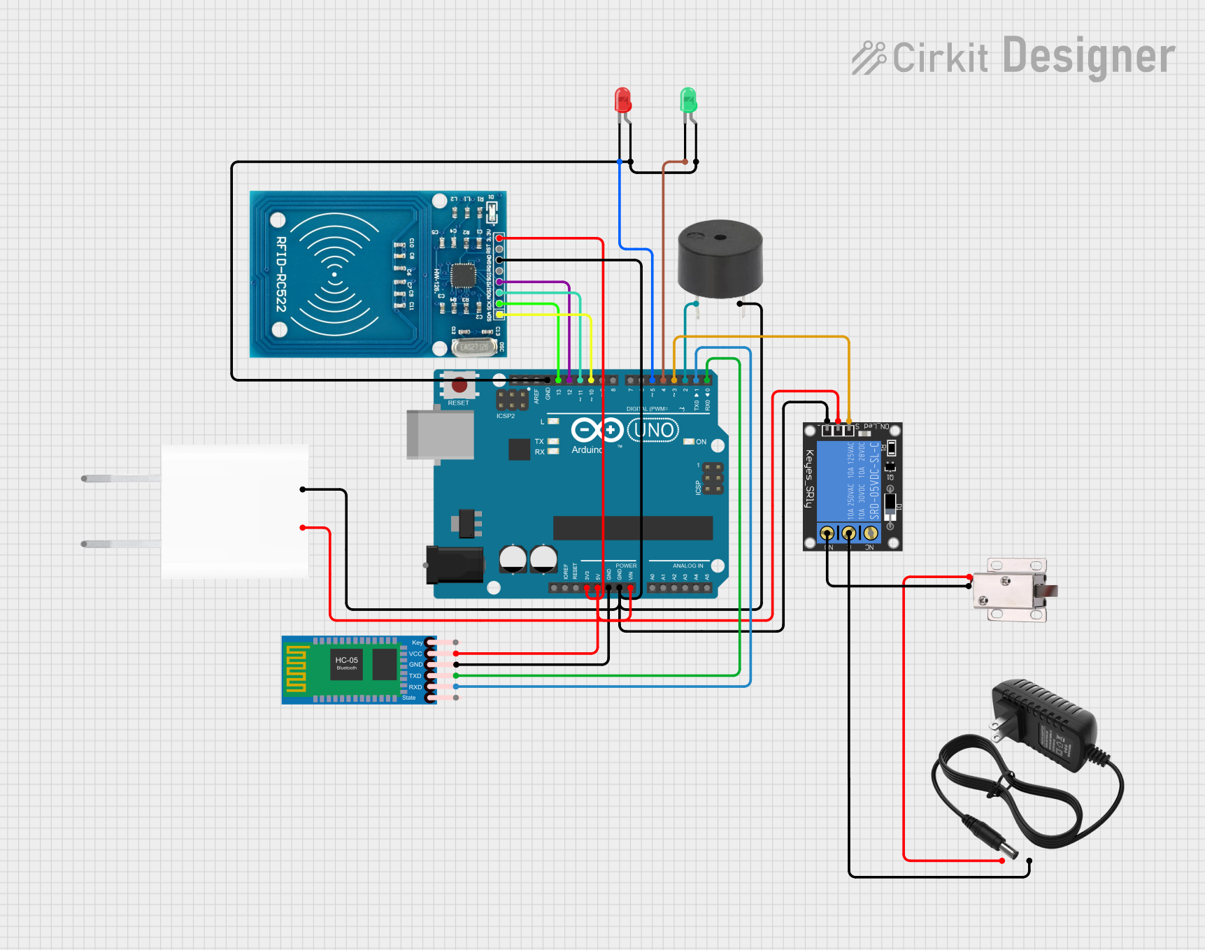 Open Project in Cirkit Designer
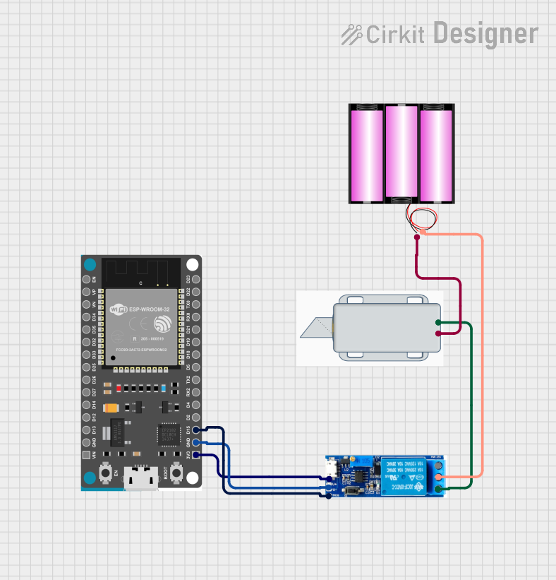 Open Project in Cirkit Designer
Explore Projects Built with 12V Solenoid Lock
Open Project in Cirkit DesignerOpen Project in Cirkit DesignerOpen Project in Cirkit DesignerOpen Project in Cirkit DesignerCommon Applications
- Electronic door locks
- Smart lockers and cabinets
- Vending machines
- Automated access control systems
- Robotics and DIY security projects
Technical Specifications
The following table outlines the key technical details of the 12V Solenoid Lock:
| Parameter | Value |
|---|---|
| Operating Voltage | 12V DC |
| Current Consumption | 0.5A to 1A (depending on load) |
| Locking Mechanism Type | Spring-loaded pin |
| Material | Metal housing, plastic core |
| Dimensions | Varies (e.g., 55mm x 40mm x 27mm) |
| Activation Time | Continuous or momentary (as required) |
| Weight | ~150g |
Pin Configuration
The 12V Solenoid Lock typically has two wires for connection:
| Wire Color | Function |
|---|---|
| Red | Positive terminal (+12V DC) |
| Black | Negative terminal (Ground) |
Usage Instructions
How to Use the 12V Solenoid Lock in a Circuit
- Power Supply: Ensure you have a stable 12V DC power supply capable of providing at least 1A of current.
- Connection:
- Connect the red wire to the positive terminal of the power supply.
- Connect the black wire to the ground terminal of the power supply.
- Control Circuit:
- Use a transistor, relay, or MOSFET to control the solenoid lock from a microcontroller or other logic-level device.
- Add a flyback diode across the solenoid terminals to protect the circuit from voltage spikes caused by the solenoid's inductive load.
- Testing:
- Apply 12V DC to the solenoid lock. The locking pin should retract, unlocking the mechanism.
- Remove the voltage to allow the spring to return the pin to its locked position.
Important Considerations
- Power Rating: Ensure your power supply can handle the current draw of the solenoid lock.
- Heat Dissipation: Avoid keeping the solenoid continuously powered for extended periods, as it may overheat.
- Flyback Diode: Always use a flyback diode (e.g., 1N4007) across the solenoid terminals to prevent damage to your circuit.
- Mounting: Secure the solenoid lock firmly to prevent movement during operation.
Example: Controlling the Solenoid Lock with an Arduino UNO
Below is an example of how to control the 12V Solenoid Lock using an Arduino UNO and an NPN transistor (e.g., 2N2222):
// Define the pin connected to the transistor's base
const int solenoidPin = 9;

void setup() {
  // Set the solenoid control pin as an output
  pinMode(solenoidPin, OUTPUT);
}

void loop() {
  // Activate the solenoid lock
  digitalWrite(solenoidPin, HIGH); // Turn on the transistor
  delay(1000);                     // Keep the lock open for 1 second

  // Deactivate the solenoid lock
  digitalWrite(solenoidPin, LOW);  // Turn off the transistor
  delay(1000);                     // Wait for 1 second before repeating
}
Circuit Notes:
- Connect the solenoid's red wire to the 12V power supply.
- Connect the solenoid's black wire to the collector of the NPN transistor.
- Connect the emitter of the transistor to ground.
- Use a 1kΩ resistor between the Arduino pin and the transistor's base.
- Place a flyback diode (e.g., 1N4007) across the solenoid terminals, with the cathode connected to the red wire.
Troubleshooting and FAQs
Common Issues and Solutions
The solenoid lock does not activate:
- Check the power supply voltage and current rating. Ensure it provides 12V DC and at least 1A.
- Verify the wiring connections, especially the polarity of the solenoid wires.
- Ensure the control circuit (e.g., transistor or relay) is functioning correctly.
The solenoid lock gets hot:
- Avoid keeping the solenoid continuously powered for long durations.
- Use a momentary activation approach to minimize heat buildup.
Voltage spikes damage the circuit:
- Ensure a flyback diode is installed across the solenoid terminals to suppress voltage spikes.
The locking pin does not return to the locked position:
- Check if the spring mechanism is obstructed or damaged.
- Ensure the solenoid is not continuously powered, as this may prevent the spring from resetting.
FAQs
Q: Can I use a 9V battery to power the solenoid lock?
A: No, a 9V battery cannot provide sufficient voltage or current to operate the solenoid lock reliably. Use a 12V DC power supply instead.
Q: Can I control the solenoid lock directly from an Arduino pin?
A: No, the Arduino pin cannot supply enough current to drive the solenoid lock. Use a transistor, relay, or MOSFET as an intermediary.
Q: What happens if I reverse the polarity of the solenoid wires?
A: Reversing the polarity may prevent the solenoid from functioning correctly. Always connect the red wire to the positive terminal and the black wire to ground.
Q: Can I use the solenoid lock outdoors?
A: The solenoid lock is not typically weatherproof. If outdoor use is required, ensure it is enclosed in a weather-resistant housing.