Cirkit Designer
Your all-in-one circuit design IDE
Home /
Component Documentation
How to Use 6 relays module: Examples, Pinouts, and Specs
Introduction
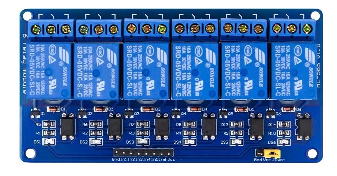
The 6 Relays Module is an electronic device that contains six individual relay switches capable of controlling multiple circuits independently. Relays are electromechanical switches that allow a low-power signal to control a higher power circuit, making them essential for interfacing microcontrollers like Arduino with high-power devices such as motors, lights, and other appliances.
Explore Projects Built with 6 relays module
DC-DC Converter and Relay Module Power Distribution System

This circuit consists of a DC-DC converter powering a 6-channel power module, which in turn supplies 5V to a 2-relay module. The power module distributes the converted voltage to the relay module, enabling it to control external devices.
Wi-Fi Controlled 4-Channel Relay System with Arduino and ESP8266
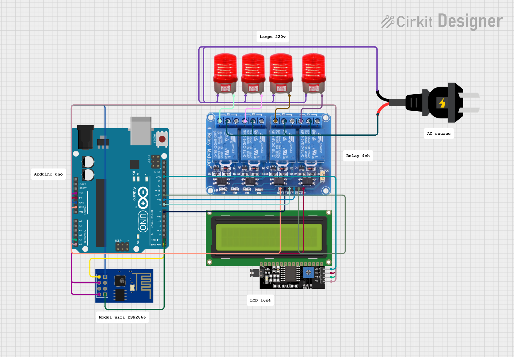
This circuit is a Wi-Fi controlled 4-channel relay system using an Arduino UNO and an ESP8266 module. The relays can be controlled via a web interface served by the ESP8266, and the status of each relay is displayed on a 16x4 I2C LCD. The relays are used to control four 220V AC red lights, and the Arduino communicates with the ESP8266 via serial communication.
Arduino and ESP32-CAM Based Fingerprint-Triggered Solenoid Lock System
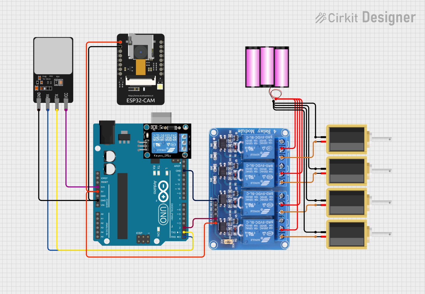
This circuit is designed for a security or access control application, featuring an Arduino UNO interfaced with a fingerprint scanner for authentication and controlling a 4-channel relay module. The relays operate multiple solenoids powered by a 12V battery, and an ESP32-CAM module is included for potential image capture capabilities.
Wi-Fi Controlled Relay System Using ESP8266

This circuit uses an ESP8266 microcontroller to control a 4-channel relay module, which can switch various loads. The ESP8266 is powered by a 12V DC supply converted from an AC source, and it interfaces with the relay module to control the relays via its digital output pins.
Explore Projects Built with 6 relays module
DC-DC Converter and Relay Module Power Distribution System
This circuit consists of a DC-DC converter powering a 6-channel power module, which in turn supplies 5V to a 2-relay module. The power module distributes the converted voltage to the relay module, enabling it to control external devices.
Wi-Fi Controlled 4-Channel Relay System with Arduino and ESP8266
This circuit is a Wi-Fi controlled 4-channel relay system using an Arduino UNO and an ESP8266 module. The relays can be controlled via a web interface served by the ESP8266, and the status of each relay is displayed on a 16x4 I2C LCD. The relays are used to control four 220V AC red lights, and the Arduino communicates with the ESP8266 via serial communication.
Arduino and ESP32-CAM Based Fingerprint-Triggered Solenoid Lock System
This circuit is designed for a security or access control application, featuring an Arduino UNO interfaced with a fingerprint scanner for authentication and controlling a 4-channel relay module. The relays operate multiple solenoids powered by a 12V battery, and an ESP32-CAM module is included for potential image capture capabilities.
Wi-Fi Controlled Relay System Using ESP8266
This circuit uses an ESP8266 microcontroller to control a 4-channel relay module, which can switch various loads. The ESP8266 is powered by a 12V DC supply converted from an AC source, and it interfaces with the relay module to control the relays via its digital output pins.
Common Applications and Use Cases
- Home automation systems
- Industrial controls
- Automotive electronics
- Robotics
Technical Specifications
Key Technical Details
- Operating Voltage: Typically 5V for the control circuit
- Switching Voltage: Up to 250VAC or 30VDC at varying current ratings
- Current Rating: Often around 10A per relay
- Control Signal: TTL compatible
Pin Configuration and Descriptions
| Pin Number | Description |
|---|---|
| 1 | IN1 (Control signal for Relay 1) |
| 2 | IN2 (Control signal for Relay 2) |
| 3 | IN3 (Control signal for Relay 3) |
| 4 | IN4 (Control signal for Relay 4) |
| 5 | IN5 (Control signal for Relay 5) |
| 6 | IN6 (Control signal for Relay 6) |
| 7 | GND (Ground) |
| 8 | VCC (Power supply for relays) |
| 9 | JD-VCC (Power supply for relay coils) |
Note: Some modules may have an opto-isolated input which separates the control circuit from the power circuit for safety and noise reduction. In such cases, JD-VCC and VCC may be separated, and an additional jumper or connection may be present.
Usage Instructions
How to Use the Component in a Circuit
- Power Supply: Connect the VCC pin to a 5V power supply and GND to the ground. If the module has a JD-VCC pin, ensure it is also connected to a 5V supply if isolation is not required.
- Control Signal: Connect the IN1 to IN6 pins to the digital outputs of a microcontroller like an Arduino.
- Load Connection: Connect the device you want to control to the Normally Open (NO) and Common (COM) terminals of the relay. For Normally Closed (NC) operation, use the NC terminal instead of NO.
Important Considerations and Best Practices
- Ensure the power supply can handle the current drawn by all relays if activated simultaneously.
- Be cautious when working with high voltage or current. Always follow safety protocols.
- Use flyback diodes when controlling inductive loads to prevent back EMF damage.
- Avoid placing sensitive electronics too close to the relays to minimize electromagnetic interference.
Example Code for Arduino UNO
// Define relay control pins
const int relayPins[] = {2, 3, 4, 5, 6, 7};

void setup() {
  // Set all the relay control pins as outputs
  for (int i = 0; i < 6; i++) {
    pinMode(relayPins[i], OUTPUT);
    digitalWrite(relayPins[i], HIGH); // Relays are usually active LOW
  }
}

void loop() {
  // Example: Turn on each relay for 1 second, then off
  for (int i = 0; i < 6; i++) {
    digitalWrite(relayPins[i], LOW); // Activate relay
    delay(1000);                      // Wait for 1 second
    digitalWrite(relayPins[i], HIGH); // Deactivate relay
    delay(1000);                      // Wait for 1 second
  }
}
Troubleshooting and FAQs
Common Issues Users Might Face
- Relay not activating: Check the control signal and power supply connections.
- Intermittent operation: Verify that the power supply is stable and can handle the current.
- Noise issues: Ensure proper isolation if using opto-isolated inputs and avoid long control signal wires.
Solutions and Tips for Troubleshooting
- Use a multimeter to check for continuity across the relay terminals when activated.
- If using an external power supply for JD-VCC, ensure the ground is connected to the Arduino's ground.
- Check for soldering issues or loose connections if the module is user-assembled.
FAQs:
- Q: Can I control the relays with a 3.3V signal?
- A: Some modules are 3.3V compatible, but check the specifications to be sure.
- Q: How do I know if the relay is active?
- A: Most modules have an LED indicator that lights up when the relay is active.
- Q: Can I use PWM to control the relays?
- A: Relays are not designed for PWM control and should only be switched on or off.