Cirkit Designer Logo
Cirkit Designer
Your all-in-one circuit design IDE
Home / 
Component Documentation

How to Use AM2320 Humitidy and Temperature Sensor: Examples, Pinouts, and Specs

Image of AM2320 Humitidy and Temperature Sensor
Cirkit Designer LogoDesign with AM2320 Humitidy and Temperature Sensor in Cirkit Designer

Introduction

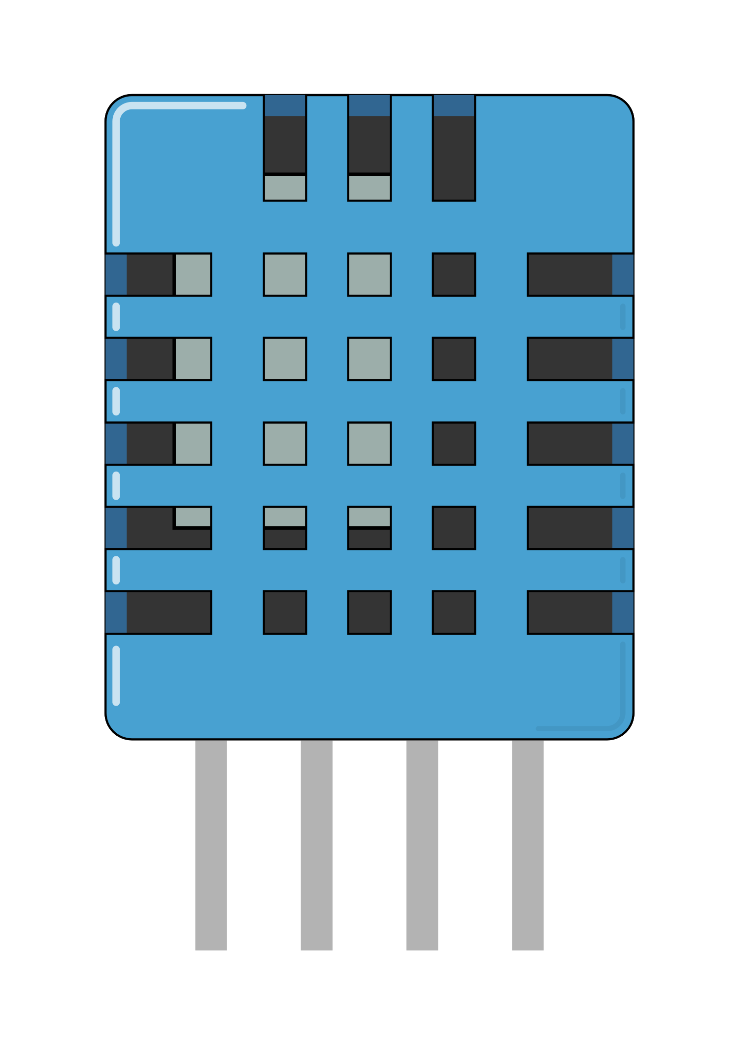
The AM2320 is a digital temperature and humidity sensor that offers high reliability and excellent long-term stability. It features a low-power consumption design, making it suitable for battery-powered applications. The sensor uses the I2C communication protocol for data transmission, allowing for easy integration with microcontrollers such as Arduino, Raspberry Pi, and others. Common applications include weather monitoring systems, HVAC (heating, ventilation, and air conditioning) control, home automation, and other environmental sensing projects.

Explore Projects Built with AM2320 Humitidy and Temperature Sensor

Use Cirkit Designer to design, explore, and prototype these projects online. Some projects support real-time simulation. Click "Open Project" to start designing instantly!
Arduino Leonardo Tiny Weather Station with DHT11 Sensor
Image of Hydroponics Project: A project utilizing AM2320 Humitidy and Temperature Sensor in a practical application
This circuit uses an Atmega32U4 microcontroller to read temperature and humidity data from a DHT11 sensor. The microcontroller is powered by an MB102 Breadboard Power Supply Module, which provides the necessary 5V and ground connections. The collected data is then printed to the serial monitor for monitoring purposes.
Cirkit Designer LogoOpen Project in Cirkit Designer
Arduino Mega 2560-Based Temperature and Humidity Monitor with DHT22 Sensor
Image of karakterisasi dht: A project utilizing AM2320 Humitidy and Temperature Sensor in a practical application
This circuit uses an Arduino Mega 2560 to read temperature and humidity data from a DHT22 sensor. The sensor is powered by the Arduino's 5V and GND pins, and its data output is connected to the Arduino's digital pin D2. The Arduino is programmed to process and potentially transmit this data.
Cirkit Designer LogoOpen Project in Cirkit Designer
Arduino Mega 2560 with Multiple DHT Sensors for Environmental Monitoring
Image of Schematic Diagram: A project utilizing AM2320 Humitidy and Temperature Sensor in a practical application
This circuit is designed to monitor temperature and humidity using two DHT22 sensors and one DHT11 sensor, all controlled by an Arduino Mega 2560. The sensors are powered by the Arduino and communicate with it through digital pins D2, D3, and D4. The provided code is a template for implementing the sensor data acquisition logic.
Cirkit Designer LogoOpen Project in Cirkit Designer
Arduino Mega 2560 Weather Station with DHT11 Sensor
Image of T5_ Group9: A project utilizing AM2320 Humitidy and Temperature Sensor in a practical application
This circuit uses an Arduino Mega 2560 R3 microcontroller to read temperature and humidity data from a DHT11 sensor. The sensor is powered by the Arduino's 5V and GND pins, and its data pin is connected to digital pin 8 of the Arduino. The Arduino runs a program that reads the sensor data and outputs it to the serial monitor.
Cirkit Designer LogoOpen Project in Cirkit Designer

Explore Projects Built with AM2320 Humitidy and Temperature Sensor

Use Cirkit Designer to design, explore, and prototype these projects online. Some projects support real-time simulation. Click "Open Project" to start designing instantly!
Image of Hydroponics Project: A project utilizing AM2320 Humitidy and Temperature Sensor in a practical application
Arduino Leonardo Tiny Weather Station with DHT11 Sensor
This circuit uses an Atmega32U4 microcontroller to read temperature and humidity data from a DHT11 sensor. The microcontroller is powered by an MB102 Breadboard Power Supply Module, which provides the necessary 5V and ground connections. The collected data is then printed to the serial monitor for monitoring purposes.
Cirkit Designer LogoOpen Project in Cirkit Designer
Image of karakterisasi dht: A project utilizing AM2320 Humitidy and Temperature Sensor in a practical application
Arduino Mega 2560-Based Temperature and Humidity Monitor with DHT22 Sensor
This circuit uses an Arduino Mega 2560 to read temperature and humidity data from a DHT22 sensor. The sensor is powered by the Arduino's 5V and GND pins, and its data output is connected to the Arduino's digital pin D2. The Arduino is programmed to process and potentially transmit this data.
Cirkit Designer LogoOpen Project in Cirkit Designer
Image of Schematic Diagram: A project utilizing AM2320 Humitidy and Temperature Sensor in a practical application
Arduino Mega 2560 with Multiple DHT Sensors for Environmental Monitoring
This circuit is designed to monitor temperature and humidity using two DHT22 sensors and one DHT11 sensor, all controlled by an Arduino Mega 2560. The sensors are powered by the Arduino and communicate with it through digital pins D2, D3, and D4. The provided code is a template for implementing the sensor data acquisition logic.
Cirkit Designer LogoOpen Project in Cirkit Designer
Image of T5_ Group9: A project utilizing AM2320 Humitidy and Temperature Sensor in a practical application
Arduino Mega 2560 Weather Station with DHT11 Sensor
This circuit uses an Arduino Mega 2560 R3 microcontroller to read temperature and humidity data from a DHT11 sensor. The sensor is powered by the Arduino's 5V and GND pins, and its data pin is connected to digital pin 8 of the Arduino. The Arduino runs a program that reads the sensor data and outputs it to the serial monitor.
Cirkit Designer LogoOpen Project in Cirkit Designer

Technical Specifications

Key Technical Details

  • Supply Voltage: 3.1V to 5.5V
  • Measuring Range (Humidity): 0 to 99.9% RH
  • Measuring Range (Temperature): -40°C to +80°C
  • Accuracy (Humidity): ±3% RH
  • Accuracy (Temperature): ±0.5°C
  • Resolution: 0.1
  • Sensing Period: 2s
  • Communication: I2C protocol

Pin Configuration and Descriptions

Pin Number Name Description
1 VDD Power supply (3.1V to 5.5V)
2 SDA I2C Data
3 GND Ground
4 SCL I2C Clock

Usage Instructions

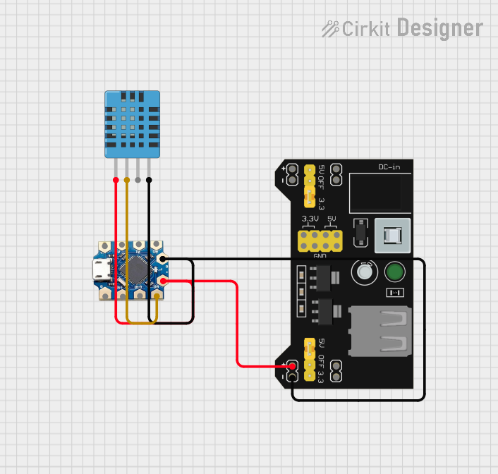
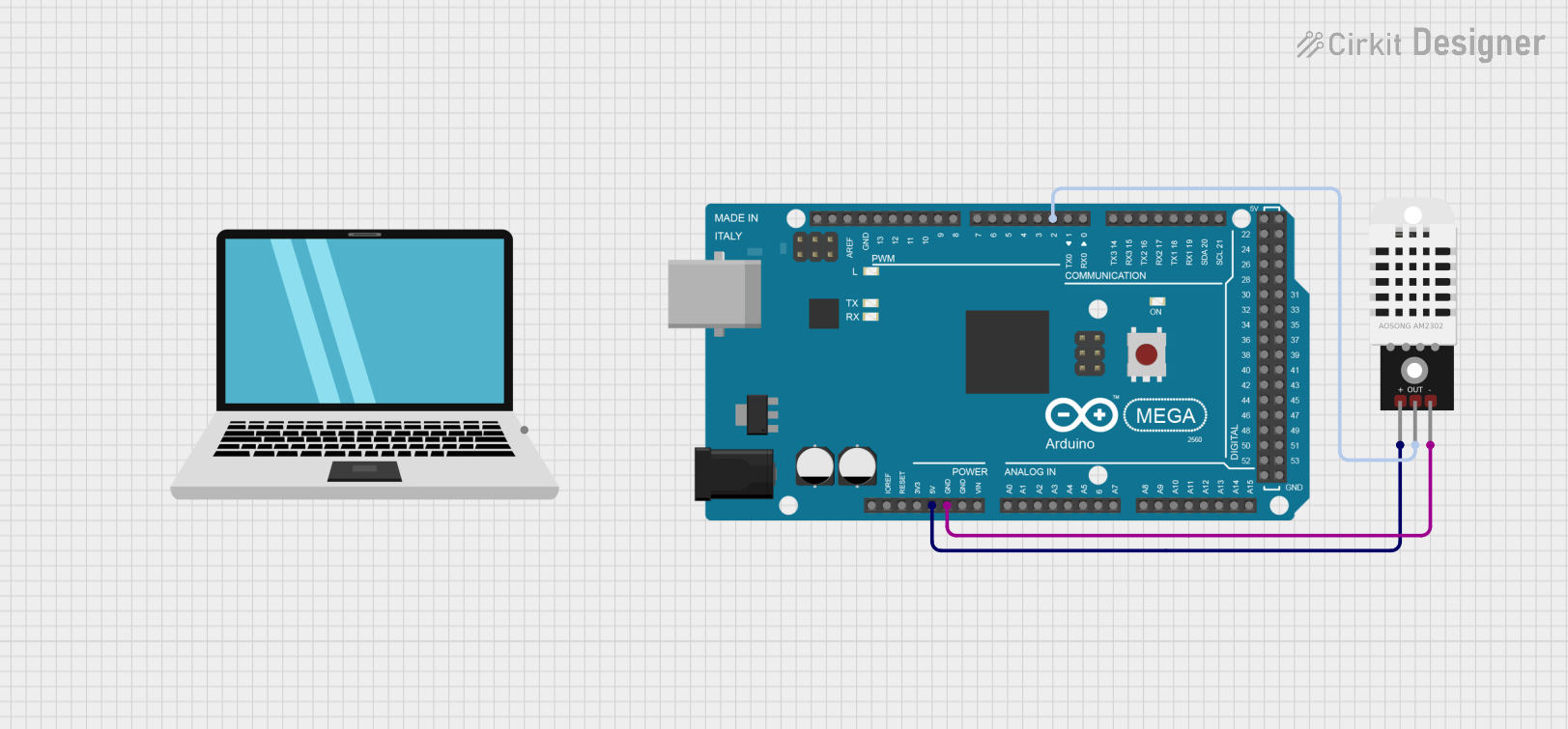
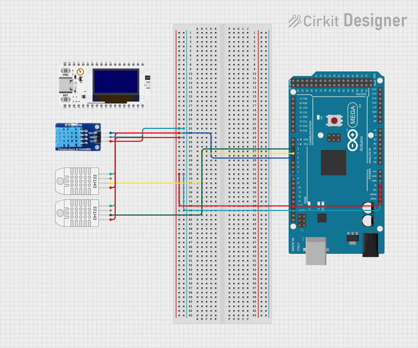
Integration with a Circuit

  1. Connect the VDD pin to the power supply (3.1V to 5.5V).
  2. Connect the GND pin to the ground of the power supply.
  3. Connect the SDA and SCL pins to the I2C data and clock lines of the microcontroller.
  4. Ensure pull-up resistors are connected to the SDA and SCL lines if they are not provided by the microcontroller board.

Best Practices

  • Place the sensor in a location that represents the environment's average temperature and humidity.
  • Avoid exposing the sensor to direct sunlight or moisture.
  • Use proper decoupling capacitors close to the sensor's power supply pins to filter out noise.
  • Ensure that the I2C bus lines are not too long to prevent signal degradation.

Example Code for Arduino UNO

#include <Wire.h>
#include <AM2320.h>

AM2320 sensor(Wire);

void setup() {
  Serial.begin(9600);
  Wire.begin();
}

void loop() {
  sensor.read();
  Serial.print("Temperature: ");
  Serial.print(sensor.temperature / 10.0);
  Serial.println(" C");
  Serial.print("Humidity: ");
  Serial.print(sensor.humidity / 10.0);
  Serial.println(" %");
  delay(2000); // Wait for 2 seconds before reading again
}

Note: The above code assumes the use of an AM2320 library for Arduino, which simplifies the process of reading data from the sensor. Make sure to install the library before uploading the code to your Arduino.

Troubleshooting and FAQs

Common Issues

  • Sensor not detected: Ensure that the sensor is correctly wired and that the I2C address is correct.
  • Inaccurate readings: Check for any environmental factors that may affect the sensor's readings, such as direct sunlight or moisture.
  • No data on serial monitor: Confirm that the correct baud rate is set in the Serial Monitor and that the Arduino board is properly connected to the computer.

Solutions and Tips

  • If the sensor is not detected, double-check the connections and ensure that the pull-up resistors are in place.
  • For inaccurate readings, recalibrate the sensor if possible or replace it if it is defective.
  • Ensure that the Arduino IDE's Serial Monitor baud rate matches the baud rate specified in the Serial.begin() function in your code.

FAQs:

Q: What is the I2C address of the AM2320? A: The default I2C address of the AM2320 is 0x5C.

Q: Can the AM2320 be used with a 3.3V system? A: Yes, the AM2320 can operate at a voltage as low as 3.1V, making it compatible with 3.3V systems.

Q: How long should I wait between measurements? A: The sensor requires a minimum of 2 seconds between measurements to ensure accurate readings.