Cirkit Designer Logo
Cirkit Designer
Your all-in-one circuit design IDE
Home / 
Component Documentation

How to Use Capacitive button: Examples, Pinouts, and Specs

Image of Capacitive button
Cirkit Designer LogoDesign with Capacitive button in Cirkit Designer

Introduction

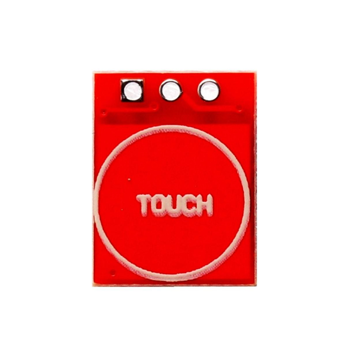
The TTP223 capacitive button, manufactured by Arduino, is a touch-sensitive switch that detects the presence of a finger or conductive object. This component enables user input without requiring mechanical movement, making it ideal for sleek, modern designs. It is widely used in touch-based interfaces, replacing traditional mechanical buttons for enhanced durability and aesthetic appeal.

Explore Projects Built with Capacitive button

Use Cirkit Designer to design, explore, and prototype these projects online. Some projects support real-time simulation. Click "Open Project" to start designing instantly!
Pushbutton-Controlled LED Circuit with Capacitor Smoothing
Image of cirkit designer project3: A project utilizing Capacitive button in a practical application
This is a simple pushbutton-controlled LED circuit with a voltage stabilization or power reserve feature provided by an electrolytic capacitor. Pressing either pushbutton will complete the circuit, allowing current to flow from the 4 x AAA batteries through the LED, causing it to illuminate.
Cirkit Designer LogoOpen Project in Cirkit Designer
Battery-Powered LED Circuit with Pushbutton Control and Capacitance Smoothing
Image of Coding and Robotics activity 3: A project utilizing Capacitive button in a practical application
This circuit consists of a 4 x AAA battery mount providing power, two pushbuttons acting as switches, an electrolytic capacitor for smoothing voltage fluctuations, and a red LED as an indicator. The LED lights up when either pushbutton is pressed, with the capacitor likely serving to debounce the pushbutton signal or provide a more stable LED operation. There is no microcontroller in this circuit, indicating a simple, direct-control user interface.
Cirkit Designer LogoOpen Project in Cirkit Designer
Arduino UNO Controlled Interface with TFT Display and Feedback Indicators
Image of Mission Control: A project utilizing Capacitive button in a practical application
This circuit features an Arduino UNO microcontroller connected to a capacitive touch TFT display for user interface, three LEDs for visual feedback, a buzzer for audio alerts, and multiple pushbuttons for user input. It is designed to interact with users through the display and buttons, control visual and audio indicators, and can be customized via the provided code template.
Cirkit Designer LogoOpen Project in Cirkit Designer
Arduino Nano-Based Capacitive Touch Controlled LED Lighting System
Image of Arduino nano touch switch: A project utilizing Capacitive button in a practical application
This circuit uses an Arduino Nano to interface with a 4-channel capacitive touch switch. Touch events are detected by the Arduino and used to control two LEDs (red and green), each with a current-limiting resistor, indicating different system states or touch responses.
Cirkit Designer LogoOpen Project in Cirkit Designer

Explore Projects Built with Capacitive button

Use Cirkit Designer to design, explore, and prototype these projects online. Some projects support real-time simulation. Click "Open Project" to start designing instantly!
Image of cirkit designer project3: A project utilizing Capacitive button in a practical application
Pushbutton-Controlled LED Circuit with Capacitor Smoothing
This is a simple pushbutton-controlled LED circuit with a voltage stabilization or power reserve feature provided by an electrolytic capacitor. Pressing either pushbutton will complete the circuit, allowing current to flow from the 4 x AAA batteries through the LED, causing it to illuminate.
Cirkit Designer LogoOpen Project in Cirkit Designer
Image of Coding and Robotics activity 3: A project utilizing Capacitive button in a practical application
Battery-Powered LED Circuit with Pushbutton Control and Capacitance Smoothing
This circuit consists of a 4 x AAA battery mount providing power, two pushbuttons acting as switches, an electrolytic capacitor for smoothing voltage fluctuations, and a red LED as an indicator. The LED lights up when either pushbutton is pressed, with the capacitor likely serving to debounce the pushbutton signal or provide a more stable LED operation. There is no microcontroller in this circuit, indicating a simple, direct-control user interface.
Cirkit Designer LogoOpen Project in Cirkit Designer
Image of Mission Control: A project utilizing Capacitive button in a practical application
Arduino UNO Controlled Interface with TFT Display and Feedback Indicators
This circuit features an Arduino UNO microcontroller connected to a capacitive touch TFT display for user interface, three LEDs for visual feedback, a buzzer for audio alerts, and multiple pushbuttons for user input. It is designed to interact with users through the display and buttons, control visual and audio indicators, and can be customized via the provided code template.
Cirkit Designer LogoOpen Project in Cirkit Designer
Image of Arduino nano touch switch: A project utilizing Capacitive button in a practical application
Arduino Nano-Based Capacitive Touch Controlled LED Lighting System
This circuit uses an Arduino Nano to interface with a 4-channel capacitive touch switch. Touch events are detected by the Arduino and used to control two LEDs (red and green), each with a current-limiting resistor, indicating different system states or touch responses.
Cirkit Designer LogoOpen Project in Cirkit Designer

Common Applications and Use Cases

  • Touch-sensitive control panels
  • Home automation systems
  • Wearable devices
  • Consumer electronics (e.g., lamps, appliances)
  • Interactive kiosks and displays

Technical Specifications

The TTP223 capacitive button is a compact and efficient touch sensor module. Below are its key technical details:

Key Technical Details

  • Operating Voltage: 2.0V to 5.5V DC
  • Operating Current: 1.5µA (low power mode), 3mA (active mode)
  • Response Time: ~60ms (fast mode), ~220ms (low power mode)
  • Output Type: Digital (active high or active low, configurable)
  • Touch Sensitivity: Adjustable via onboard capacitor
  • Operating Temperature: -30°C to +85°C
  • Dimensions: 11mm x 15mm (module size)

Pin Configuration and Descriptions

The TTP223 module typically has 3 pins. Below is the pinout and description:

Pin Name Description
1 VCC Power supply input (2.0V to 5.5V DC).
2 GND Ground connection.
3 OUT Digital output pin. Outputs HIGH or LOW based on touch detection.

Usage Instructions

How to Use the TTP223 in a Circuit

  1. Power the Module: Connect the VCC pin to a 3.3V or 5V power source and the GND pin to ground.
  2. Connect the Output: Connect the OUT pin to a microcontroller input pin (e.g., Arduino UNO digital pin) or directly to a circuit that requires a digital signal.
  3. Adjust Sensitivity (Optional): If needed, adjust the touch sensitivity by changing the onboard capacitor (default is 0.1µF).
  4. Configure Output Mode (Optional): The TTP223 supports two modes:
    • Active High: The OUT pin goes HIGH when touched.
    • Active Low: The OUT pin goes LOW when touched. This can be configured by soldering the appropriate jumper pads on the module.

Important Considerations and Best Practices

  • Avoid Noise Interference: Place the module away from high-frequency components to prevent false triggering.
  • Stable Power Supply: Use a decoupling capacitor (e.g., 0.1µF) near the VCC pin to ensure stable operation.
  • Touch Surface: For optimal performance, ensure the touch surface is clean and free of debris.
  • Output Pull-Up/Down Resistor: If the output is connected to a microcontroller, ensure the pin is configured with the appropriate pull-up or pull-down resistor.

Example: Connecting to an Arduino UNO

Below is an example of how to connect and use the TTP223 with an Arduino UNO:

Circuit Connections

  • VCC → 5V on Arduino
  • GND → GND on Arduino
  • OUT → Digital Pin 2 on Arduino

Arduino Code

// Define the pin connected to the TTP223 OUT pin
const int touchPin = 2; 
const int ledPin = 13; // Built-in LED on Arduino UNO

void setup() {
  pinMode(touchPin, INPUT); // Set touchPin as input
  pinMode(ledPin, OUTPUT);  // Set ledPin as output
  Serial.begin(9600);       // Initialize serial communication
}

void loop() {
  int touchState = digitalRead(touchPin); // Read the state of the touch sensor

  if (touchState == HIGH) {
    // If touch is detected, turn on the LED
    digitalWrite(ledPin, HIGH);
    Serial.println("Touch detected!");
  } else {
    // If no touch is detected, turn off the LED
    digitalWrite(ledPin, LOW);
  }

  delay(100); // Small delay to debounce the touch input
}

Troubleshooting and FAQs

Common Issues and Solutions

  1. False Triggering or Unstable Output

    • Cause: Electrical noise or unstable power supply.
    • Solution: Add a decoupling capacitor (e.g., 0.1µF) near the VCC pin and ensure proper grounding.
  2. No Response to Touch

    • Cause: Incorrect wiring or insufficient sensitivity.
    • Solution: Double-check the connections and ensure the VCC and GND pins are properly connected. If needed, increase the sensitivity by replacing the onboard capacitor with a higher value.
  3. Output Always HIGH or LOW

    • Cause: Incorrect configuration of the output mode.
    • Solution: Verify the jumper pad configuration on the module and ensure it matches the desired output mode (active high or active low).

FAQs

Q: Can the TTP223 detect touch through non-conductive materials?
A: Yes, the TTP223 can detect touch through thin non-conductive materials like plastic or glass. However, the thickness and material type may affect sensitivity.

Q: How do I increase the touch sensitivity?
A: Increase the value of the onboard capacitor (default is 0.1µF). For example, replacing it with a 0.22µF capacitor will increase sensitivity.

Q: Can I use multiple TTP223 modules in the same circuit?
A: Yes, multiple modules can be used. Ensure each module has a stable power supply and is placed away from sources of interference.

Q: Is the TTP223 compatible with 3.3V systems?
A: Yes, the TTP223 operates within a voltage range of 2.0V to 5.5V, making it compatible with both 3.3V and 5V systems.