Cirkit Designer Logo
Cirkit Designer
Your all-in-one circuit design IDE
Home / 
Component Documentation

How to Use HR961160C Ethernet Board: Examples, Pinouts, and Specs

Image of HR961160C Ethernet Board
Cirkit Designer LogoDesign with HR961160C Ethernet Board in Cirkit Designer

Introduction

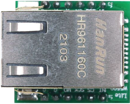
The HR961160C Ethernet Board is a compact and robust networking module designed to provide Ethernet connectivity to embedded systems. It is based on the HR961160C Ethernet controller, which integrates an Ethernet PHY layer and an RJ45 connector, making it suitable for a wide range of Internet of Things (IoT) applications, home automation, industrial control, and any project requiring network connectivity.

Explore Projects Built with HR961160C Ethernet Board

Use Cirkit Designer to design, explore, and prototype these projects online. Some projects support real-time simulation. Click "Open Project" to start designing instantly!
STM32F4 and ENC28J60 Ethernet-Enabled Microcontroller Project
Image of youssef: A project utilizing HR961160C Ethernet Board in a practical application
This circuit integrates an STM32F4 BlackPill microcontroller with an ENC28J60 Ethernet Board to enable Ethernet connectivity. The microcontroller communicates with the Ethernet board via SPI, with connections for power, ground, and SPI signals (SI, SO, SCK, and CS). The provided code is a basic template for further development.
Cirkit Designer LogoOpen Project in Cirkit Designer
ESP32 and W5500 Ethernet Module Controlled 8-Channel Relay
Image of ESP32 38Pin 8 Channel Relay USB-C: A project utilizing HR961160C Ethernet Board in a practical application
This circuit enables Ethernet connectivity and device control through an ESP32 microcontroller. It uses the W5500 Ethernet module for network communication and controls an 8-channel relay module for switching external devices or loads.
Cirkit Designer LogoOpen Project in Cirkit Designer
ESP8266 NodeMCU with LoRa and RS-485 Communication and Ethernet Connectivity
Image of Wiring Diagram LoRa: A project utilizing HR961160C Ethernet Board in a practical application
This circuit serves as a multi-protocol communication hub featuring two ESP8266 NodeMCUs for processing, each connected to a LoRa Ra-02 SX1278 for long-range wireless communication. One NodeMCU is also connected to an RS-485 module for serial communication and a W5500 Ethernet module for network connectivity, with MB102 modules supplying power.
Cirkit Designer LogoOpen Project in Cirkit Designer
ESP32-Based Environmental Monitoring and Home Automation System with Ethernet Connectivity
Image of ESP32 30Pin 3Phase AC Box W5500 Ethernet Standard: A project utilizing HR961160C Ethernet Board in a practical application
This circuit features an ESP32 microcontroller interfaced with a W5500 Ethernet module for network connectivity, a DHT22 sensor for measuring temperature and humidity, a ZMPT101B module for AC voltage sensing, and an Adafruit SHTC3 sensor for additional temperature and humidity readings. The ESP32 also controls a 4-channel relay module for switching external devices. The sensors and Ethernet module communicate with the ESP32 via GPIO pins, with the W5500 using SPI and the SHTC3 using I2C. Common ground and power lines are shared among the components.
Cirkit Designer LogoOpen Project in Cirkit Designer

Explore Projects Built with HR961160C Ethernet Board

Use Cirkit Designer to design, explore, and prototype these projects online. Some projects support real-time simulation. Click "Open Project" to start designing instantly!
Image of youssef: A project utilizing HR961160C Ethernet Board in a practical application
STM32F4 and ENC28J60 Ethernet-Enabled Microcontroller Project
This circuit integrates an STM32F4 BlackPill microcontroller with an ENC28J60 Ethernet Board to enable Ethernet connectivity. The microcontroller communicates with the Ethernet board via SPI, with connections for power, ground, and SPI signals (SI, SO, SCK, and CS). The provided code is a basic template for further development.
Cirkit Designer LogoOpen Project in Cirkit Designer
Image of ESP32 38Pin 8 Channel Relay USB-C: A project utilizing HR961160C Ethernet Board in a practical application
ESP32 and W5500 Ethernet Module Controlled 8-Channel Relay
This circuit enables Ethernet connectivity and device control through an ESP32 microcontroller. It uses the W5500 Ethernet module for network communication and controls an 8-channel relay module for switching external devices or loads.
Cirkit Designer LogoOpen Project in Cirkit Designer
Image of Wiring Diagram LoRa: A project utilizing HR961160C Ethernet Board in a practical application
ESP8266 NodeMCU with LoRa and RS-485 Communication and Ethernet Connectivity
This circuit serves as a multi-protocol communication hub featuring two ESP8266 NodeMCUs for processing, each connected to a LoRa Ra-02 SX1278 for long-range wireless communication. One NodeMCU is also connected to an RS-485 module for serial communication and a W5500 Ethernet module for network connectivity, with MB102 modules supplying power.
Cirkit Designer LogoOpen Project in Cirkit Designer
Image of ESP32 30Pin 3Phase AC Box W5500 Ethernet Standard: A project utilizing HR961160C Ethernet Board in a practical application
ESP32-Based Environmental Monitoring and Home Automation System with Ethernet Connectivity
This circuit features an ESP32 microcontroller interfaced with a W5500 Ethernet module for network connectivity, a DHT22 sensor for measuring temperature and humidity, a ZMPT101B module for AC voltage sensing, and an Adafruit SHTC3 sensor for additional temperature and humidity readings. The ESP32 also controls a 4-channel relay module for switching external devices. The sensors and Ethernet module communicate with the ESP32 via GPIO pins, with the W5500 using SPI and the SHTC3 using I2C. Common ground and power lines are shared among the components.
Cirkit Designer LogoOpen Project in Cirkit Designer

Common Applications and Use Cases

  • IoT devices
  • Networked sensors and actuators
  • Home automation systems
  • Industrial control systems
  • Remote data logging and monitoring

Technical Specifications

The HR961160C Ethernet Board is designed to operate with a wide range of microcontrollers and microprocessors. Below are the key technical specifications:

Specification Detail
Supply Voltage 3.3V DC
Operating Voltage 3.3V logic level
Network Interface 10/100 Ethernet
Connector Integrated RJ45 with LEDs
PHY Integrated Ethernet PHY
Dimensions 21mm x 16mm x 1.6mm

Pin Configuration and Descriptions

Pin Number Name Description
1 VCC Power supply (3.3V)
2 GND Ground
3 TX+ Transmit positive signal
4 TX- Transmit negative signal
5 RX+ Receive positive signal
6 RX- Receive negative signal
7 LED+ Anode for link/activity LED
8 LED- Cathode for link/activity LED

Usage Instructions

Connecting to a Circuit

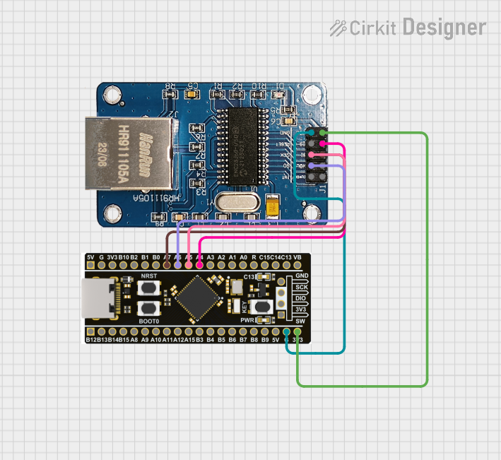
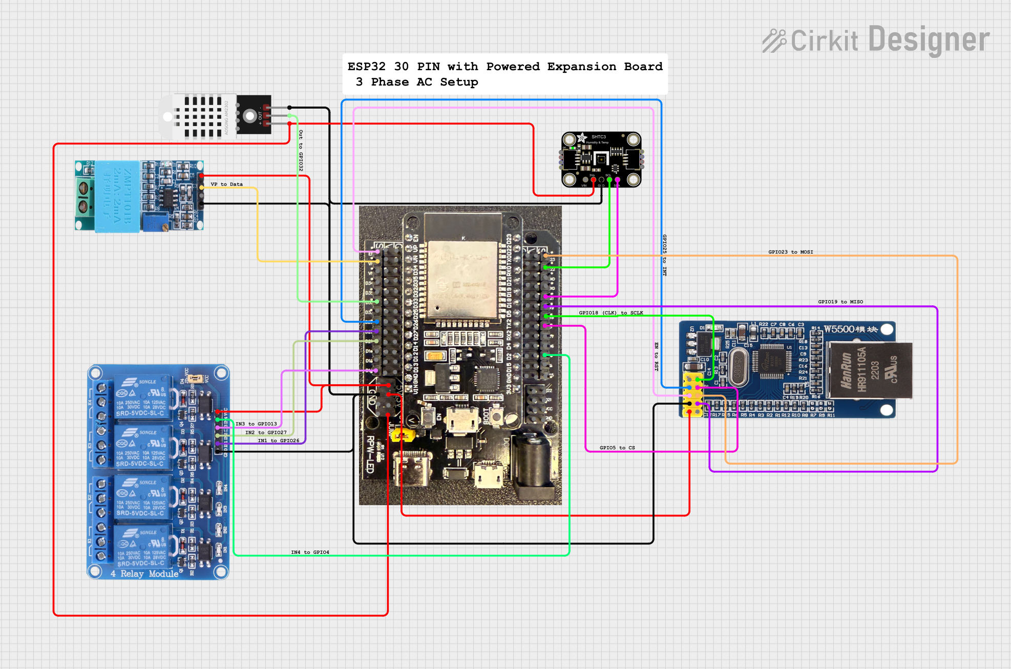
To use the HR961160C Ethernet Board in a circuit, follow these steps:

  1. Connect the VCC pin to a 3.3V power supply.
  2. Connect the GND pin to the ground of your power supply.
  3. Connect the TX+ and TX- pins to the transmit pins of your microcontroller's Ethernet peripheral.
  4. Connect the RX+ and RX- pins to the receive pins of your microcontroller's Ethernet peripheral.
  5. Optionally, connect the LED+ and LED- to drive the link/activity indicator LEDs through your microcontroller if desired.

Important Considerations and Best Practices

  • Ensure that the power supply is stable and clean to avoid damaging the board.
  • Use proper ESD precautions when handling the Ethernet Board to prevent static damage.
  • Keep the Ethernet cable length within the recommended maximum length of 100 meters to ensure signal integrity.
  • Use twisted-pair Ethernet cables (Cat5e or higher) for connections.

Troubleshooting and FAQs

Common Issues

  • No Link Detected: Ensure that the Ethernet cable is properly connected and that the router/switch is powered on.
  • Intermittent Connectivity: Check for loose connections and inspect the Ethernet cable for damage.
  • Board Not Responding: Verify that the power supply is 3.3V and that the board is correctly oriented in the circuit.

Solutions and Tips for Troubleshooting

  • Double-check wiring against the pin configuration table.
  • Use a multimeter to verify the presence of the 3.3V supply on the VCC pin.
  • Ensure that the ground connection is secure and common to all devices in the network.
  • If using with an Arduino UNO, ensure that a level shifter is used since the UNO operates at 5V logic levels.

FAQs

  • Q: Can I use the HR961160C Ethernet Board with a 5V microcontroller?

    • A: Yes, but you will need to use a level shifter to convert the 5V signals to 3.3V to avoid damaging the board.
  • Q: Does the board support Power over Ethernet (PoE)?

    • A: No, the HR961160C Ethernet Board does not support PoE natively. You would need an additional PoE module.
  • Q: Are drivers required to use this board?

    • A: The board will typically be used with a microcontroller that has a built-in Ethernet library. Ensure that the library supports the HR961160C chipset.

Example Code for Arduino UNO

Below is an example of how to initialize the Ethernet board with an Arduino UNO. Note that this code assumes the use of a level shifter and an appropriate Ethernet library that supports the HR961160C chipset.

#include <Ethernet.h>

// MAC address for the Ethernet shield
byte mac[] = { 0xDE, 0xAD, 0xBE, 0xEF, 0xFE, 0xED };

void setup() {
  // Open serial communications
  Serial.begin(9600);

  // Start the Ethernet connection
  if (Ethernet.begin(mac) == 0) {
    Serial.println("Failed to configure Ethernet using DHCP");
    // No point in carrying on, so do nothing forevermore:
    for (;;)
      ;
  }
  // Print the local IP address
  Serial.println(Ethernet.localIP());
}

void loop() {
  // Main code loop
}

Remember to adjust the mac array to a unique MAC address within your network. This example uses DHCP to obtain an IP address. If you need to set a static IP address, consult the Ethernet library documentation for the correct method.