How to Use ESP32-S3-LCD-1.47: Examples, Pinouts, and Specs
Introduction
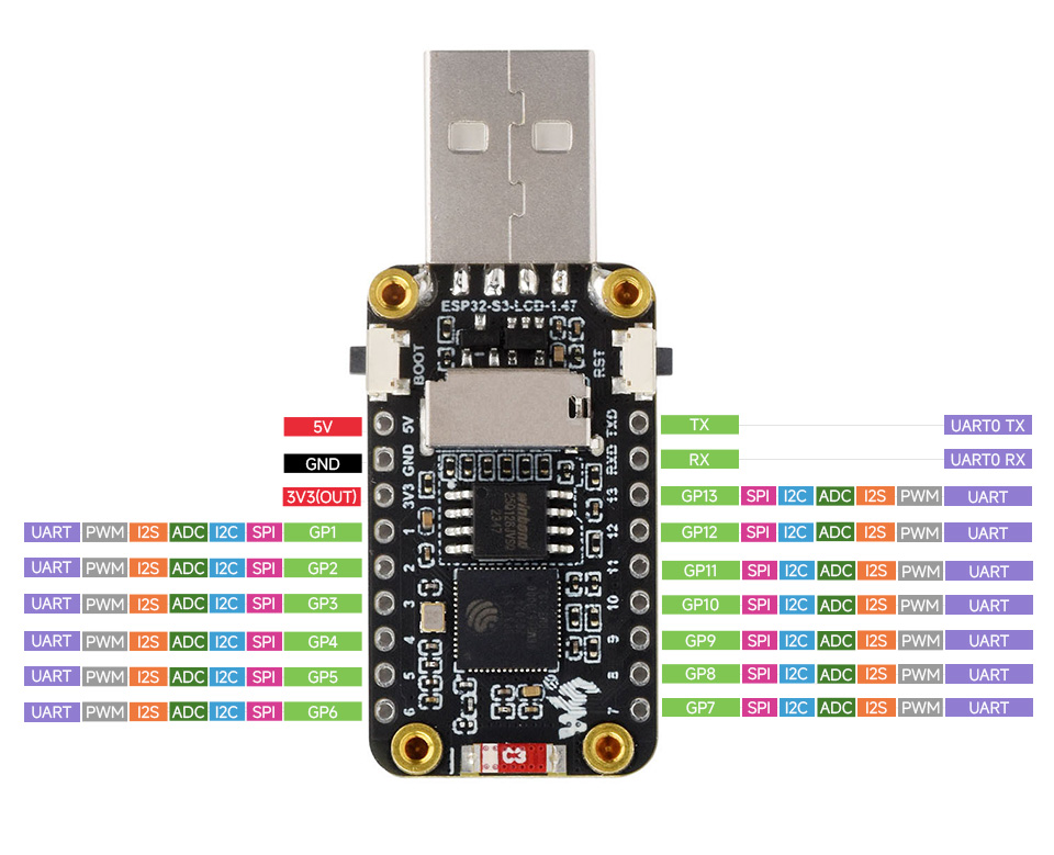
The ESP32-S3-LCD-1.47 is a compact development board manufactured by Waveshare, featuring the ESP32-S3 microcontroller. This board integrates Wi-Fi and Bluetooth capabilities, making it ideal for IoT applications. It is equipped with a 1.47-inch LCD screen, enabling visual output for user interfaces, data visualization, or debugging purposes. The board is designed for developers who need a powerful microcontroller with display functionality in a compact form factor.
Explore Projects Built with ESP32-S3-LCD-1.47
Explore Projects Built with ESP32-S3-LCD-1.47
Common Applications and Use Cases
- IoT devices with visual feedback (e.g., smart home controllers, wearables)
- Portable data loggers with graphical output
- Educational projects and prototyping
- Industrial control panels with real-time data visualization
- Wireless communication projects using Wi-Fi and Bluetooth
Technical Specifications
Key Technical Details
| Parameter | Value |
|---|---|
| Microcontroller | ESP32-S3 |
| Wireless Connectivity | Wi-Fi 802.11 b/g/n, Bluetooth 5.0 |
| Display | 1.47-inch LCD, 172x320 resolution |
| Flash Memory | 16 MB |
| PSRAM | 8 MB |
| Operating Voltage | 3.3V |
| Input Voltage Range | 5V (via USB-C) |
| GPIO Pins | 20 (configurable for various peripherals) |
| Communication Interfaces | UART, SPI, I2C, I2S, PWM |
| Dimensions | 54mm x 25mm |
Pin Configuration and Descriptions
| Pin Name | Pin Number | Description |
|---|---|---|
| 3V3 | 1 | 3.3V power output |
| GND | 2 | Ground |
| GPIO0 | 3 | General-purpose I/O, boot mode selection |
| GPIO1 | 4 | General-purpose I/O |
| GPIO2 | 5 | General-purpose I/O |
| GPIO3 | 6 | General-purpose I/O |
| TXD0 | 7 | UART0 transmit |
| RXD0 | 8 | UART0 receive |
| SCL | 9 | I2C clock |
| SDA | 10 | I2C data |
| MOSI | 11 | SPI master-out, slave-in |
| MISO | 12 | SPI master-in, slave-out |
| SCK | 13 | SPI clock |
| CS | 14 | SPI chip select |
| LCD_RST | 15 | LCD reset |
| LCD_DC | 16 | LCD data/command control |
| LCD_BL | 17 | LCD backlight control |
| EN | 18 | Enable pin for power management |
| USB_DM | 19 | USB data minus |
| USB_DP | 20 | USB data plus |
Usage Instructions
How to Use the Component in a Circuit
Powering the Board:
- Connect the board to a 5V power source using the USB-C port. The onboard voltage regulator will step down the voltage to 3.3V for the ESP32-S3 and peripherals.
Connecting Peripherals:
- Use the GPIO pins to connect sensors, actuators, or other devices. Ensure the voltage levels of connected devices are compatible with the 3.3V logic of the ESP32-S3.
Programming the Board:
- Install the ESP32 board package in the Arduino IDE or use the ESP-IDF (Espressif IoT Development Framework) for advanced development.
- Connect the board to your computer via USB-C and select the appropriate COM port in your development environment.
Using the LCD:
- The LCD is controlled via SPI. Use the provided pins (MOSI, MISO, SCK, CS, LCD_RST, LCD_DC, LCD_BL) to interface with the display.
- Install the required libraries (e.g., TFT_eSPI) in your development environment to simplify display control.
Important Considerations and Best Practices
- Power Supply: Ensure a stable 5V power source to avoid voltage fluctuations that may affect performance.
- GPIO Voltage Levels: Do not exceed 3.3V on GPIO pins to prevent damage to the microcontroller.
- Heat Management: The ESP32-S3 may generate heat during operation. Ensure proper ventilation if used in an enclosed space.
- Firmware Updates: Regularly update the firmware to benefit from performance improvements and bug fixes.
Example Code for Arduino IDE
Below is an example code snippet to initialize the LCD and display a simple message:
#include <TFT_eSPI.h> // Include the TFT_eSPI library

TFT_eSPI tft = TFT_eSPI(); // Create an instance of the display

void setup() {
  tft.init(); // Initialize the display
  tft.setRotation(1); // Set display orientation
  tft.fillScreen(TFT_BLACK); // Clear the screen with black color
  tft.setTextColor(TFT_WHITE, TFT_BLACK); // Set text color and background
  tft.setTextSize(2); // Set text size

  tft.setCursor(10, 10); // Set cursor position
  tft.println("Hello, ESP32-S3!"); // Print message to the display
}

void loop() {
  // Add your main code here
}
Troubleshooting and FAQs
Common Issues and Solutions
The board does not power on:
- Ensure the USB-C cable is properly connected and functional.
- Verify the power source provides sufficient current (at least 500mA).
Unable to upload code:
- Check that the correct COM port is selected in the Arduino IDE or ESP-IDF.
- Ensure the board is in bootloader mode by holding the BOOT button while pressing the RESET button.
LCD does not display anything:
- Verify the SPI connections and ensure the correct pins are defined in your code.
- Check that the LCD backlight (LCD_BL) pin is properly configured.
Wi-Fi or Bluetooth not working:
- Ensure the correct credentials are provided for Wi-Fi.
- Verify that the Bluetooth device is discoverable and within range.
FAQs
Q: Can I power the board using a battery?
A: Yes, you can use a 3.7V LiPo battery connected to the appropriate pins, but ensure the battery voltage is regulated to 3.3V for the ESP32-S3.
Q: What is the maximum range of the Wi-Fi and Bluetooth?
A: The Wi-Fi range is approximately 30 meters indoors and 100 meters outdoors. Bluetooth range depends on the environment but typically extends up to 10 meters.
Q: Can I use the board without the LCD?
A: Yes, the ESP32-S3 can function independently of the LCD. Simply avoid initializing the display in your code.
Q: Is the board compatible with MicroPython?
A: Yes, the ESP32-S3 supports MicroPython. You can flash the MicroPython firmware to the board and use it for development.