How to Use 12V to 5V USB-C Connection: Examples, Pinouts, and Specs
Introduction
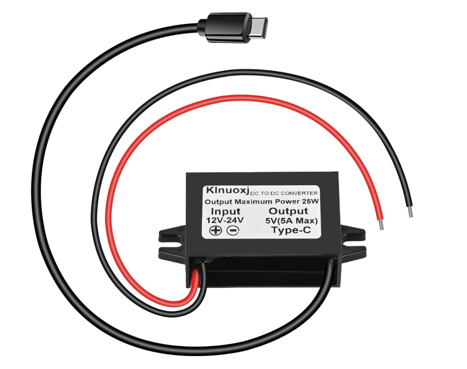
The 12V to 5V USB-C Connection by Klnuoxj (Manufacturer Part ID: DC 12V/24V to 5V USB C Step Down Converter) is a compact and efficient power conversion module. It steps down a 12V or 24V input voltage to a stable 5V output, making it ideal for powering USB-C devices such as smartphones, tablets, single-board computers, and other peripherals.
This module is designed for use in automotive, industrial, and DIY electronics projects where a reliable 5V USB-C power source is required.
Explore Projects Built with 12V to 5V USB-C Connection


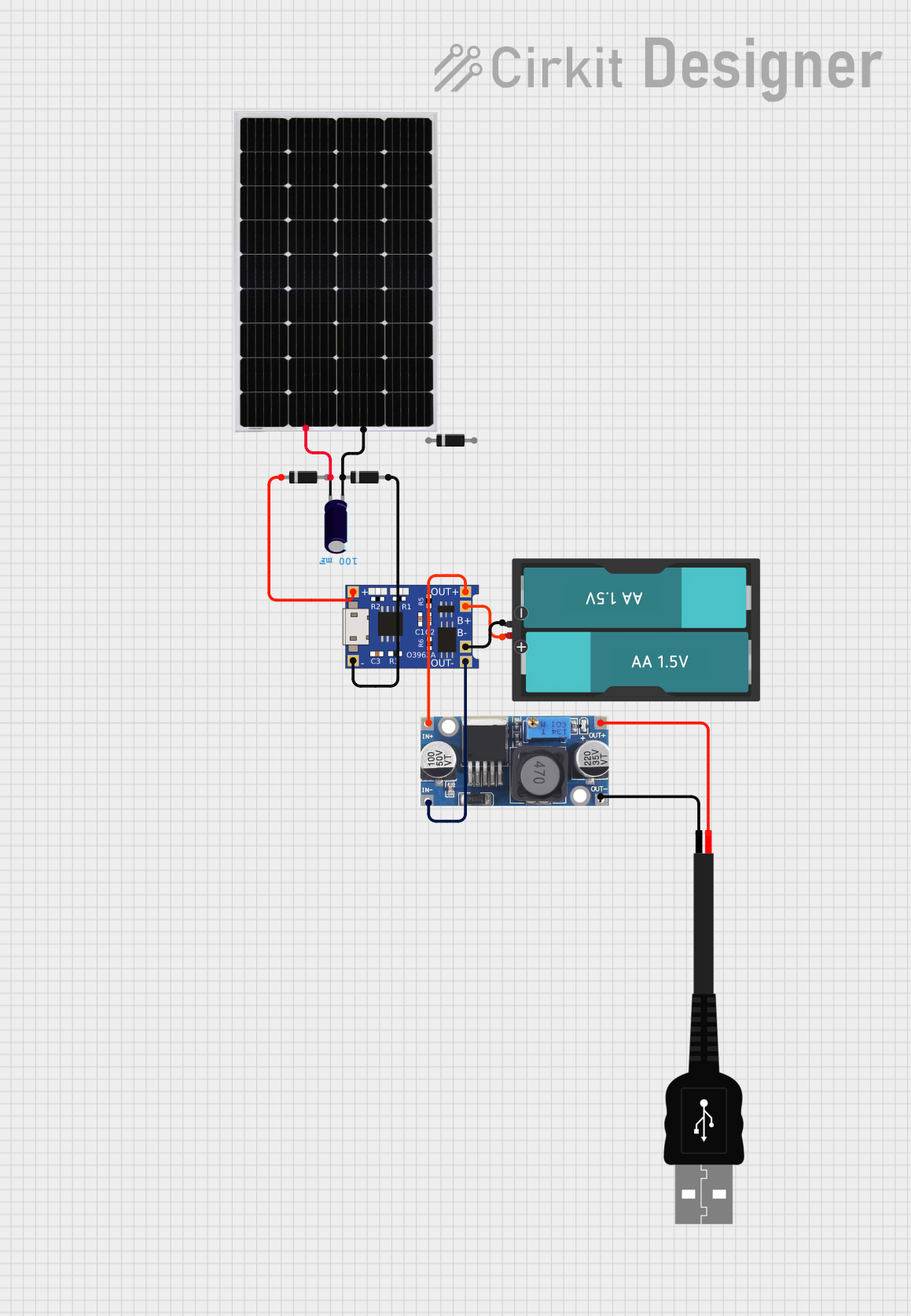

Explore Projects Built with 12V to 5V USB-C Connection
Common Applications and Use Cases
- Powering USB-C devices in vehicles (e.g., charging smartphones or tablets)
- Supplying power to Raspberry Pi or Arduino boards
- Integrating into custom electronics projects requiring a 5V USB-C output
- Industrial applications where 12V or 24V systems need to power USB-C devices
Technical Specifications
Key Technical Details
| Parameter | Specification |
|---|---|
| Input Voltage Range | 12V to 24V DC |
| Output Voltage | 5V DC (USB-C) |
| Output Current | Up to 3A |
| Efficiency | ≥ 90% |
| Operating Temperature | -40°C to +85°C |
| Dimensions | 46mm x 26mm x 14mm |
| Weight | 20g |
| Protection Features | Over-voltage, over-current, short-circuit |
Pin Configuration and Descriptions
| Pin/Connector Name | Type | Description |
|---|---|---|
| Input (+) | Input (Wire) | Positive DC input (12V or 24V) |
| Input (-) | Input (Wire) | Negative DC input (Ground) |
| USB-C Port | Output | 5V DC output for USB-C devices |
Usage Instructions
How to Use the Component in a Circuit
Connect the Input Wires:
- Attach the red wire to the positive terminal of your 12V or 24V DC power source.
- Attach the black wire to the negative terminal (ground) of your power source.
Connect the USB-C Device:
- Plug your USB-C device (e.g., smartphone, Raspberry Pi) into the USB-C port of the module.
Power On:
- Turn on the 12V or 24V power source. The module will automatically step down the voltage to 5V and supply it to the connected USB-C device.
Important Considerations and Best Practices
- Ensure the input voltage is within the specified range (12V to 24V). Exceeding this range may damage the module.
- Do not exceed the maximum output current of 3A to avoid overheating or triggering the over-current protection.
- Mount the module in a well-ventilated area to ensure proper heat dissipation, especially in high-current applications.
- Use high-quality wires and connectors to minimize voltage drops and ensure reliable operation.
- If using the module in a vehicle, ensure proper grounding to avoid electrical noise or interference.
Example: Using with an Arduino UNO
The module can be used to power an Arduino UNO via its USB port. Below is an example of how to connect the module and upload a simple sketch to blink an LED.
Wiring Diagram
- Connect the module's input wires to a 12V DC power source.
- Plug the USB-C output into the Arduino UNO's USB port.
Arduino Code
// Simple LED Blink Example for Arduino UNO
// This code blinks the onboard LED connected to pin 13.

void setup() {
  pinMode(13, OUTPUT); // Set pin 13 as an output
}

void loop() {
  digitalWrite(13, HIGH); // Turn the LED on
  delay(1000);            // Wait for 1 second
  digitalWrite(13, LOW);  // Turn the LED off
  delay(1000);            // Wait for 1 second
}
Troubleshooting and FAQs
Common Issues and Solutions
| Issue | Possible Cause | Solution |
|---|---|---|
| No output voltage on USB-C port | Incorrect input voltage or loose wires | Verify input voltage is 12V-24V and check connections. |
| Device not charging or powering on | Exceeding maximum current limit | Ensure the connected device draws ≤ 3A. |
| Module overheating | High current draw or poor ventilation | Reduce load or improve airflow around the module. |
| Electrical noise or interference | Poor grounding or noisy power source | Ensure proper grounding and use a filtered power source. |
FAQs
Can this module be used with a 24V battery system?
- Yes, the module supports input voltages up to 24V DC.
Is the USB-C port compatible with fast charging?
- No, this module provides a fixed 5V output and does not support fast charging protocols like Power Delivery (PD) or Quick Charge (QC).
Can I use this module outdoors?
- The module is not waterproof. If used outdoors, ensure it is enclosed in a weatherproof housing.
What happens if the input voltage exceeds 24V?
- The module may be damaged. Always ensure the input voltage is within the specified range.
Can I use this module to power a Raspberry Pi?
- Yes, the module can provide sufficient power for most Raspberry Pi models, as long as the total current draw does not exceed 3A.
This documentation provides all the necessary details to effectively use the 12V to 5V USB-C Connection module by Klnuoxj. For further assistance, refer to the manufacturer's datasheet or contact their support team.