Cirkit Designer Logo
Cirkit Designer
Your all-in-one circuit design IDE
Home / 
Component Documentation

How to Use Adafruit Hallowing M4: Examples, Pinouts, and Specs
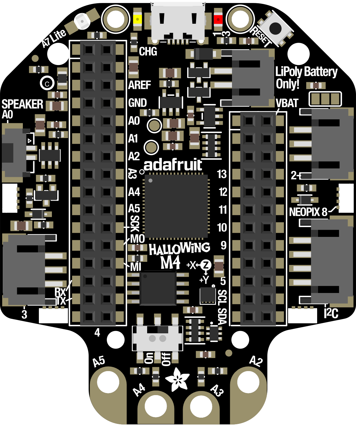

Image of Adafruit Hallowing M4
Cirkit Designer LogoDesign with Adafruit Hallowing M4 in Cirkit Designer

Introduction

The Adafruit Hallowing M4 (Manufacturer Part ID: 4300) is a powerful microcontroller board designed for wearable and interactive projects. It features the ATSAMD51 microcontroller, built-in RGB LED, and support for CircuitPython, Arduino, and MakeCode. With its compact design and versatile features, the Hallowing M4 is ideal for creating IoT devices, interactive art, and wearable electronics.

Explore Projects Built with Adafruit Hallowing M4
Use Cirkit Designer to design, explore, and prototype these projects online. Some projects support real-time simulation. Click "Open Project" to start designing instantly!
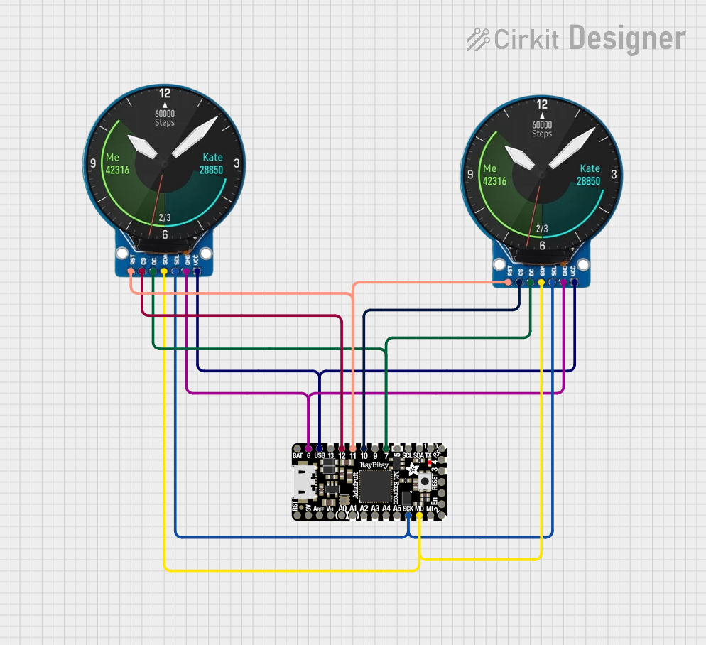
Adafruit ItsyBitsy M4 Dual GC9A01 Display Animated Eyes
Image of Eyes: A project utilizing Adafruit Hallowing M4 in a practical application
This circuit features an Adafruit ItsyBitsy M4 microcontroller connected to two GC9A01 displays. The microcontroller drives the displays to render animated eyes, with the code handling eye movements, blinks, and iris scaling. The displays share common control signals, and the microcontroller coordinates their operation to create synchronized visual effects.
Cirkit Designer LogoOpen Project in Cirkit Designer
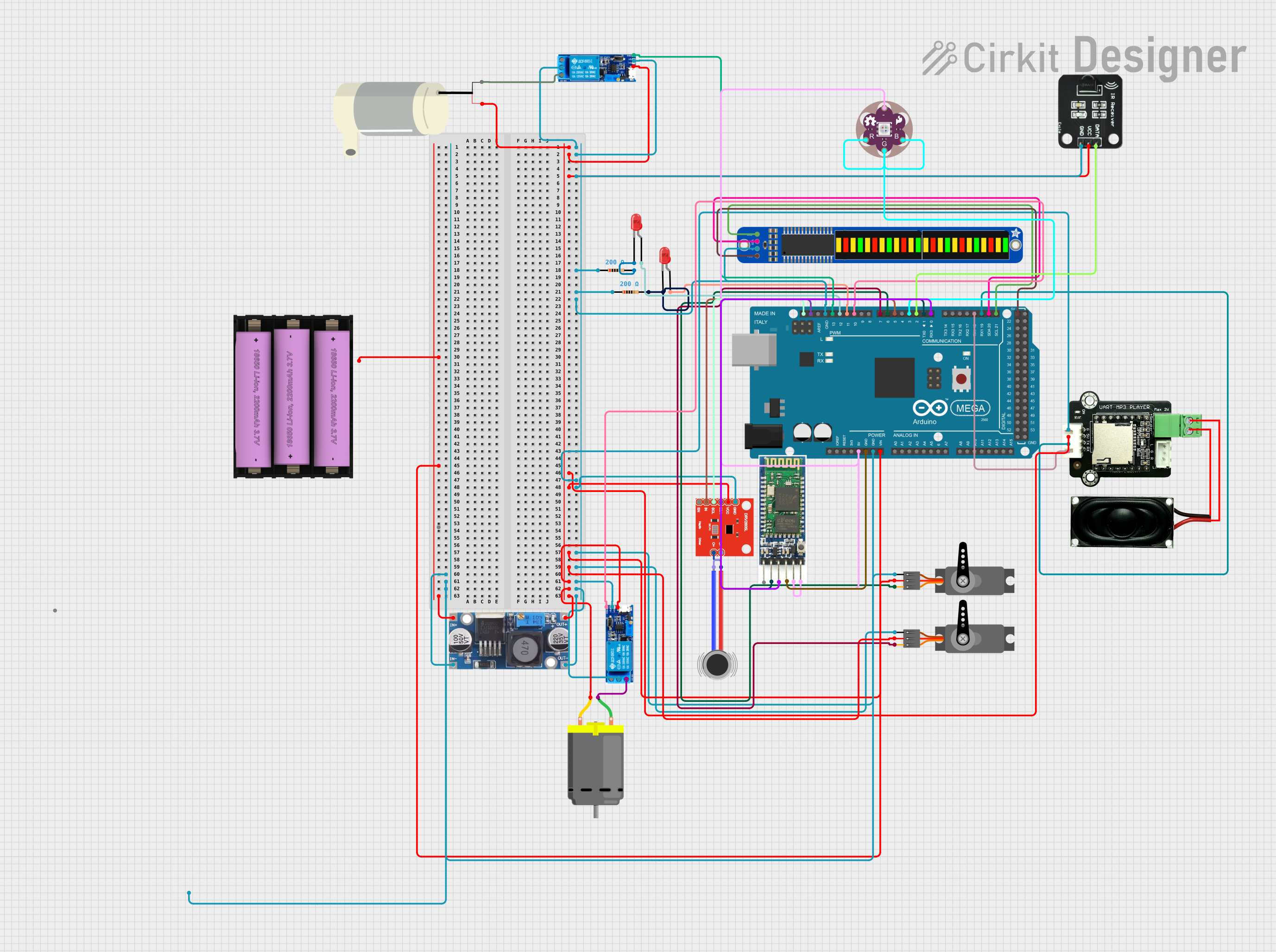
Arduino Mega 2560 Controlled Ghostbuster Trap Prop with MP3 Player and Haptic Feedback
Image of Trap Wiring: A project utilizing Adafruit Hallowing M4 in a practical application
This circuit is designed to simulate a Ghostbuster trap prop with various interactive features. It includes an Arduino Mega 2560 to control a sequence of events such as playing audio tracks through an MP3 player module, creating vibrations with a haptic motor driver and DC motors, displaying patterns on a bi-color 24-bar LED bargraph, moving servos, and activating a relay-controlled water pump. The sequence is initiated by an IR receiver, and the circuit incorporates LEDs, resistors, a step-down buck converter for voltage regulation, and a Bluetooth module for potential wireless control.
Cirkit Designer LogoOpen Project in Cirkit Designer
ATmega328P-Based Sensor Hub with OLED Display and LIDAR
Image of TILTPCB: A project utilizing Adafruit Hallowing M4 in a practical application
This circuit features an Mtiny Uno ATmega328P microcontroller as its central processing unit, interfacing with a variety of sensors and peripherals. It includes a 0.96" OLED display and an MPU6050 accelerometer/gyroscope for user interface and motion sensing, respectively. The circuit also integrates a TF LUNA LIDAR for distance measurement, a DHT11 sensor for temperature and humidity readings, and uses a 9V battery with a 7805 voltage regulator for power management. Communication with a computer for programming and data exchange is facilitated by an Adafruit FTDI Friend module.
Cirkit Designer LogoOpen Project in Cirkit Designer
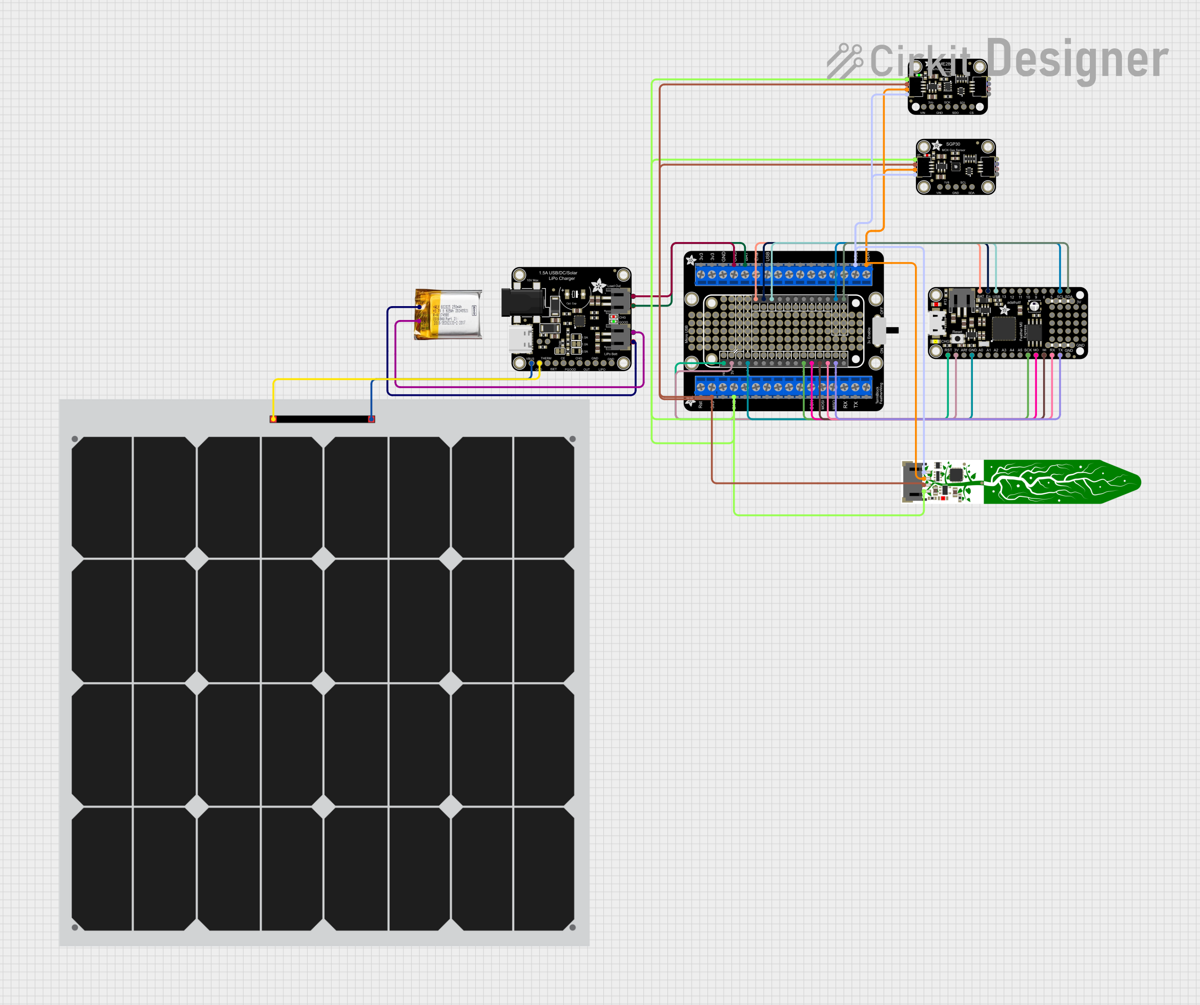
Solar-Powered Environmental Data Logger with Adafruit Feather M0 Express
Image of Lake Thoreau Monitoring Station: A project utilizing Adafruit Hallowing M4 in a practical application
This circuit is designed for environmental data collection and logging, utilizing an Adafruit Feather M0 Express microcontroller as the central processing unit. It interfaces with a BME280 sensor for atmospheric temperature, humidity, and pressure measurements, an SGP30 sensor for monitoring air quality (eCO2 and TVOC), and a STEMMA soil sensor for detecting soil moisture and temperature. The system is powered by a solar panel and a 3.7v LiPo battery, managed by an Adafruit BQ24074 Solar-DC-USB Lipo Charger, and provides easy access to the microcontroller's connections through an Adafruit Terminal Breakout FeatherWing.
Cirkit Designer LogoOpen Project in Cirkit Designer

Explore Projects Built with Adafruit Hallowing M4

Use Cirkit Designer to design, explore, and prototype these projects online. Some projects support real-time simulation. Click "Open Project" to start designing instantly!
Image of Eyes: A project utilizing Adafruit Hallowing M4 in a practical application
Adafruit ItsyBitsy M4 Dual GC9A01 Display Animated Eyes
This circuit features an Adafruit ItsyBitsy M4 microcontroller connected to two GC9A01 displays. The microcontroller drives the displays to render animated eyes, with the code handling eye movements, blinks, and iris scaling. The displays share common control signals, and the microcontroller coordinates their operation to create synchronized visual effects.
Cirkit Designer LogoOpen Project in Cirkit Designer
Image of Trap Wiring: A project utilizing Adafruit Hallowing M4 in a practical application
Arduino Mega 2560 Controlled Ghostbuster Trap Prop with MP3 Player and Haptic Feedback
This circuit is designed to simulate a Ghostbuster trap prop with various interactive features. It includes an Arduino Mega 2560 to control a sequence of events such as playing audio tracks through an MP3 player module, creating vibrations with a haptic motor driver and DC motors, displaying patterns on a bi-color 24-bar LED bargraph, moving servos, and activating a relay-controlled water pump. The sequence is initiated by an IR receiver, and the circuit incorporates LEDs, resistors, a step-down buck converter for voltage regulation, and a Bluetooth module for potential wireless control.
Cirkit Designer LogoOpen Project in Cirkit Designer
Image of TILTPCB: A project utilizing Adafruit Hallowing M4 in a practical application
ATmega328P-Based Sensor Hub with OLED Display and LIDAR
This circuit features an Mtiny Uno ATmega328P microcontroller as its central processing unit, interfacing with a variety of sensors and peripherals. It includes a 0.96" OLED display and an MPU6050 accelerometer/gyroscope for user interface and motion sensing, respectively. The circuit also integrates a TF LUNA LIDAR for distance measurement, a DHT11 sensor for temperature and humidity readings, and uses a 9V battery with a 7805 voltage regulator for power management. Communication with a computer for programming and data exchange is facilitated by an Adafruit FTDI Friend module.
Cirkit Designer LogoOpen Project in Cirkit Designer
Image of Lake Thoreau Monitoring Station: A project utilizing Adafruit Hallowing M4 in a practical application
Solar-Powered Environmental Data Logger with Adafruit Feather M0 Express
This circuit is designed for environmental data collection and logging, utilizing an Adafruit Feather M0 Express microcontroller as the central processing unit. It interfaces with a BME280 sensor for atmospheric temperature, humidity, and pressure measurements, an SGP30 sensor for monitoring air quality (eCO2 and TVOC), and a STEMMA soil sensor for detecting soil moisture and temperature. The system is powered by a solar panel and a 3.7v LiPo battery, managed by an Adafruit BQ24074 Solar-DC-USB Lipo Charger, and provides easy access to the microcontroller's connections through an Adafruit Terminal Breakout FeatherWing.
Cirkit Designer LogoOpen Project in Cirkit Designer

Common Applications and Use Cases

  • Wearable electronics and costumes
  • Interactive art installations
  • IoT (Internet of Things) devices
  • Educational projects and prototyping
  • Audio-visual effects and animations

Technical Specifications

Key Technical Details

Specification Value
Microcontroller ATSAMD51J19 Cortex M4 @ 120 MHz
Flash Memory 8 MB SPI Flash
RAM 192 KB
Power Supply 3.3V (regulated) or 5V via USB
Connectivity USB Type-C, I2C, SPI, UART
Built-in Features RGB LED, Light Sensor, Accelerometer
Programming Support CircuitPython, Arduino, MakeCode
Dimensions 50mm x 50mm

Pin Configuration and Descriptions

The Adafruit Hallowing M4 has a variety of pins for connecting peripherals and sensors. Below is the pinout description:

Pin Name Description
3V3 3.3V power output for external components
GND Ground connection
A0 - A5 Analog input pins (can also be used as digital I/O)
D0 - D13 Digital I/O pins
SDA I2C Data Line
SCL I2C Clock Line
TX UART Transmit Line
RX UART Receive Line
SPI (MOSI/MISO) SPI communication pins (Master Out Slave In / Master In Slave Out)
USB USB Type-C for power, programming, and data transfer

Usage Instructions

How to Use the Component in a Circuit

  1. Powering the Board:

    • Connect the Hallowing M4 to a USB power source using a USB Type-C cable.
    • Alternatively, supply 3.3V or 5V to the power pins (3V3 or USB pin).
  2. Programming the Board:

    • Install CircuitPython or Arduino IDE on your computer.
    • For CircuitPython, copy the .uf2 firmware file to the board's USB drive.
    • For Arduino, install the Adafruit SAMD board package and select "Adafruit Hallowing M4" as the board type.
  3. Connecting Peripherals:

    • Use the GPIO pins to connect sensors, LEDs, or other components.
    • Ensure proper voltage levels and use pull-up or pull-down resistors if required.
  4. Running Code:

    • Write your code in CircuitPython or Arduino.
    • Save the script as code.py (for CircuitPython) or upload it via the Arduino IDE.

Important Considerations and Best Practices

  • Power Supply: Ensure the board is powered within its voltage range (3.3V or 5V).
  • Pin Usage: Avoid exceeding the current limits of GPIO pins (typically 7mA per pin).
  • Static Protection: Handle the board with care to avoid damage from static electricity.
  • Firmware Updates: Keep the firmware updated for optimal performance and compatibility.

Example Code for Arduino UNO

Below is an example of how to control the built-in RGB LED using the Arduino IDE:

// Include the Adafruit NeoPixel library
#include <Adafruit_NeoPixel.h>

// Define the pin connected to the RGB LED
#define RGB_PIN 8

// Create a NeoPixel object with 1 LED
Adafruit_NeoPixel rgb = Adafruit_NeoPixel(1, RGB_PIN, NEO_GRB + NEO_KHZ800);

void setup() {
  rgb.begin(); // Initialize the RGB LED
  rgb.show();  // Turn off all LEDs initially
}

void loop() {
  // Set the RGB LED to red
  rgb.setPixelColor(0, rgb.Color(255, 0, 0)); // Red color
  rgb.show();                                // Update the LED
  delay(1000);                               // Wait for 1 second

  // Set the RGB LED to green
  rgb.setPixelColor(0, rgb.Color(0, 255, 0)); // Green color
  rgb.show();                                 // Update the LED
  delay(1000);                                // Wait for 1 second

  // Set the RGB LED to blue
  rgb.setPixelColor(0, rgb.Color(0, 0, 255)); // Blue color
  rgb.show();                                 // Update the LED
  delay(1000);                                // Wait for 1 second
}

Troubleshooting and FAQs

Common Issues Users Might Face

  1. Board Not Recognized by Computer:

    • Ensure the USB cable is data-capable (not just for charging).
    • Check if the board is in bootloader mode by double-pressing the reset button.
  2. Code Not Running:

    • Verify that the script is named code.py for CircuitPython.
    • Check for syntax errors or missing libraries in your code.
  3. RGB LED Not Lighting Up:

    • Confirm the correct pin is defined in the code.
    • Ensure the NeoPixel library is installed in the Arduino IDE.
  4. Overheating:

    • Avoid drawing excessive current from the GPIO pins.
    • Check for short circuits in your wiring.

Solutions and Tips for Troubleshooting

  • Reset the Board: Double-press the reset button to enter bootloader mode and re-upload the firmware.
  • Check Connections: Ensure all wires and components are securely connected.
  • Update Libraries: Use the latest versions of Adafruit libraries for compatibility.
  • Consult Documentation: Refer to the Adafruit Hallowing M4 product page for additional resources and support.

By following this documentation, you can effectively utilize the Adafruit Hallowing M4 for your projects and troubleshoot common issues with ease.