Cirkit Designer Logo
Cirkit Designer
Your all-in-one circuit design IDE
Home / 
Component Documentation

How to Use Adafruit ItsyBitsy RP2040: Examples, Pinouts, and Specs

Image of Adafruit ItsyBitsy RP2040
Cirkit Designer LogoDesign with Adafruit ItsyBitsy RP2040 in Cirkit Designer

Introduction

The Adafruit ItsyBitsy RP2040 is a small, powerful microcontroller board that harnesses the capabilities of the Raspberry Pi RP2040 chip. This board is designed for makers and hobbyists who need a compact, yet feature-rich, development platform for their projects. With its versatility, the ItsyBitsy RP2040 is ideal for applications in robotics, Internet of Things (IoT), wearable devices, and more.

Explore Projects Built with Adafruit ItsyBitsy RP2040

Use Cirkit Designer to design, explore, and prototype these projects online. Some projects support real-time simulation. Click "Open Project" to start designing instantly!
Adafruit QT Py RP2040 Development Board for Custom Projects
Image of perfboard: A project utilizing Adafruit ItsyBitsy RP2040 in a practical application
The circuit consists of a single Adafruit QT Py RP2040 microcontroller with no external connections or additional components. It appears to be a standalone setup, possibly for initial testing or programming purposes.
Cirkit Designer LogoOpen Project in Cirkit Designer
Battery-Powered Smart Light with Proximity Sensor and OLED Display using Adafruit QT Py RP2040
Image of lab: A project utilizing Adafruit ItsyBitsy RP2040 in a practical application
This circuit is a portable, battery-powered system featuring an Adafruit QT Py RP2040 microcontroller that interfaces with an OLED display, a proximity sensor, an accelerometer, and an RGB LED strip. The system is powered by a lithium-ion battery with a step-up boost converter to provide 5V for the LED strip, and it includes a toggle switch for power control. The microcontroller communicates with the sensors and display via I2C.
Cirkit Designer LogoOpen Project in Cirkit Designer
Battery-Powered Smart Sensor Hub with Adafruit QT Py RP2040
Image of wearable final: A project utilizing Adafruit ItsyBitsy RP2040 in a practical application
This circuit features an Adafruit QT Py RP2040 microcontroller interfaced with an APDS9960 proximity sensor, an MPU6050 accelerometer and gyroscope, and an OLED display via I2C communication. It also includes a buzzer controlled by the microcontroller and is powered by a 3.7V LiPo battery with a toggle switch for power control.
Cirkit Designer LogoOpen Project in Cirkit Designer
Battery-Powered Sensor Hub with Adafruit QT Py RP2040 and OLED Display
Image of 512: A project utilizing Adafruit ItsyBitsy RP2040 in a practical application
This circuit features an Adafruit QT Py RP2040 microcontroller interfacing with an MPU-6050 accelerometer, an Adafruit APDS-9960 sensor, and a 0.96" OLED display via I2C communication. It is powered by a 3.7V LiPo battery and includes a green LED with a current-limiting resistor connected to an analog pin of the microcontroller.
Cirkit Designer LogoOpen Project in Cirkit Designer

Explore Projects Built with Adafruit ItsyBitsy RP2040

Use Cirkit Designer to design, explore, and prototype these projects online. Some projects support real-time simulation. Click "Open Project" to start designing instantly!
Image of perfboard: A project utilizing Adafruit ItsyBitsy RP2040 in a practical application
Adafruit QT Py RP2040 Development Board for Custom Projects
The circuit consists of a single Adafruit QT Py RP2040 microcontroller with no external connections or additional components. It appears to be a standalone setup, possibly for initial testing or programming purposes.
Cirkit Designer LogoOpen Project in Cirkit Designer
Image of lab: A project utilizing Adafruit ItsyBitsy RP2040 in a practical application
Battery-Powered Smart Light with Proximity Sensor and OLED Display using Adafruit QT Py RP2040
This circuit is a portable, battery-powered system featuring an Adafruit QT Py RP2040 microcontroller that interfaces with an OLED display, a proximity sensor, an accelerometer, and an RGB LED strip. The system is powered by a lithium-ion battery with a step-up boost converter to provide 5V for the LED strip, and it includes a toggle switch for power control. The microcontroller communicates with the sensors and display via I2C.
Cirkit Designer LogoOpen Project in Cirkit Designer
Image of wearable final: A project utilizing Adafruit ItsyBitsy RP2040 in a practical application
Battery-Powered Smart Sensor Hub with Adafruit QT Py RP2040
This circuit features an Adafruit QT Py RP2040 microcontroller interfaced with an APDS9960 proximity sensor, an MPU6050 accelerometer and gyroscope, and an OLED display via I2C communication. It also includes a buzzer controlled by the microcontroller and is powered by a 3.7V LiPo battery with a toggle switch for power control.
Cirkit Designer LogoOpen Project in Cirkit Designer
Image of 512: A project utilizing Adafruit ItsyBitsy RP2040 in a practical application
Battery-Powered Sensor Hub with Adafruit QT Py RP2040 and OLED Display
This circuit features an Adafruit QT Py RP2040 microcontroller interfacing with an MPU-6050 accelerometer, an Adafruit APDS-9960 sensor, and a 0.96" OLED display via I2C communication. It is powered by a 3.7V LiPo battery and includes a green LED with a current-limiting resistor connected to an analog pin of the microcontroller.
Cirkit Designer LogoOpen Project in Cirkit Designer

Technical Specifications

Key Technical Details

  • Microcontroller: Raspberry Pi RP2040
  • Clock Speed: Up to 133 MHz
  • Flash Memory: 8 MB
  • RAM: 264 KB
  • GPIO Pins: 23 digital I/O pins
  • Analog Inputs: 3 12-bit ADC channels
  • PWM Outputs: 16 channels
  • Voltage Supply: 5V via USB or 3.3V to 5V via VIN pin
  • Logic Level: 3.3V
  • Interfaces: UART, I2C, SPI
  • USB: USB-C connector for power and data
  • Dimensions: 36mm x 17.8mm x 4.7mm

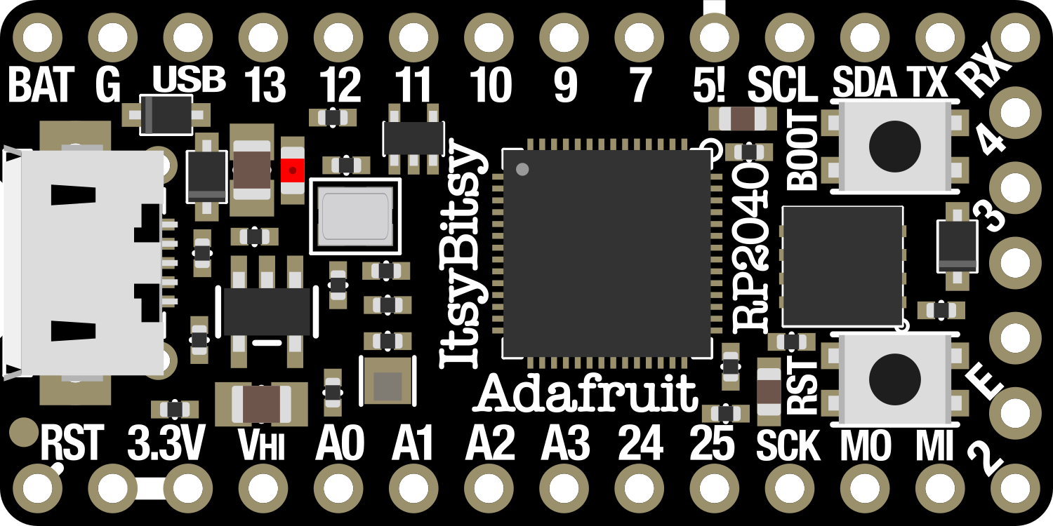
Pin Configuration and Descriptions

Pin Number Name Description
1 GND Ground
2 VBUS USB input voltage (5V)
3 3V3 3.3V output from the onboard regulator
4-7 D0-D3 General Purpose I/O pins, D0 can be used for UART RX
8-9 SDA/SCL I2C Data/Clock pins
10-12 D4-D6 General Purpose I/O pins, D5 can be used for UART TX
13 D7 General Purpose I/O pin, can also be used for SPI SCK
14-16 D8-D10 General Purpose I/O pins, D10 can be used for SPI CS
17 D11 General Purpose I/O pin, can also be used for SPI MISO
18 D12 General Purpose I/O pin, can also be used for SPI MOSI
19-21 D13-D15 General Purpose I/O pins, D13 can be used for LED
22-23 A0-A1 Analog Input pins, can also be used as digital I/O
24 A2 Analog Input pin, can also be used as digital I/O, DAC output
25 VIN Voltage input for the board, 3.3V to 5V

Usage Instructions

Setting Up the ItsyBitsy RP2040

  1. Connect the ItsyBitsy RP2040 to your computer using a USB-C cable.
  2. Install the necessary drivers and board support package for the RP2040 in your Integrated Development Environment (IDE), such as the Arduino IDE or Thonny Python IDE.
  3. Select the Adafruit ItsyBitsy RP2040 from the list of available boards in your IDE.

Programming the ItsyBitsy RP2040

  • The ItsyBitsy RP2040 can be programmed using C/C++ via the Arduino IDE or MicroPython/Python via Thonny or other Python IDEs.
  • Ensure that you select the correct board and port before uploading your code.

Best Practices

  • Always disconnect the ItsyBitsy RP2040 from power before making or altering connections.
  • Use a current limiting resistor when connecting LEDs to GPIO pins.
  • Avoid applying more than 3.3V to any of the I/O pins to prevent damage to the board.

Example Code for Arduino UNO

Here is a simple example of blinking an LED on pin D13 using the Arduino IDE:

// Define the LED pin
const int ledPin = 13;

void setup() {
  // Initialize the LED pin as an output
  pinMode(ledPin, OUTPUT);
}

void loop() {
  // Turn the LED on
  digitalWrite(ledPin, HIGH);
  // Wait for one second
  delay(1000);
  // Turn the LED off
  digitalWrite(ledPin, LOW);
  // Wait for one second
  delay(1000);
}

Troubleshooting and FAQs

Common Issues

  • Board not recognized: Ensure that you have installed the correct drivers and selected the right board in your IDE.
  • Code not uploading: Check the USB cable and port. Make sure the board is properly powered.
  • I/O pin not working: Verify that the pin is not being used by another peripheral and that it's configured correctly in your code.

FAQs

Q: Can I power the ItsyBitsy RP2040 with a battery? A: Yes, you can power it with a battery connected to the VIN pin, provided the voltage is within the 3.3V to 5V range.

Q: Is the ItsyBitsy RP2040 compatible with Raspberry Pi accessories? A: No, it is not directly compatible with Raspberry Pi accessories as it has a different form factor and pinout.

Q: How do I reset the board? A: You can reset the board by briefly connecting the RST pin to the GND pin.

For further assistance, refer to the Adafruit ItsyBitsy RP2040 forums and community resources.