How to Use MH-ET Live Scanner: Examples, Pinouts, and Specs
Introduction
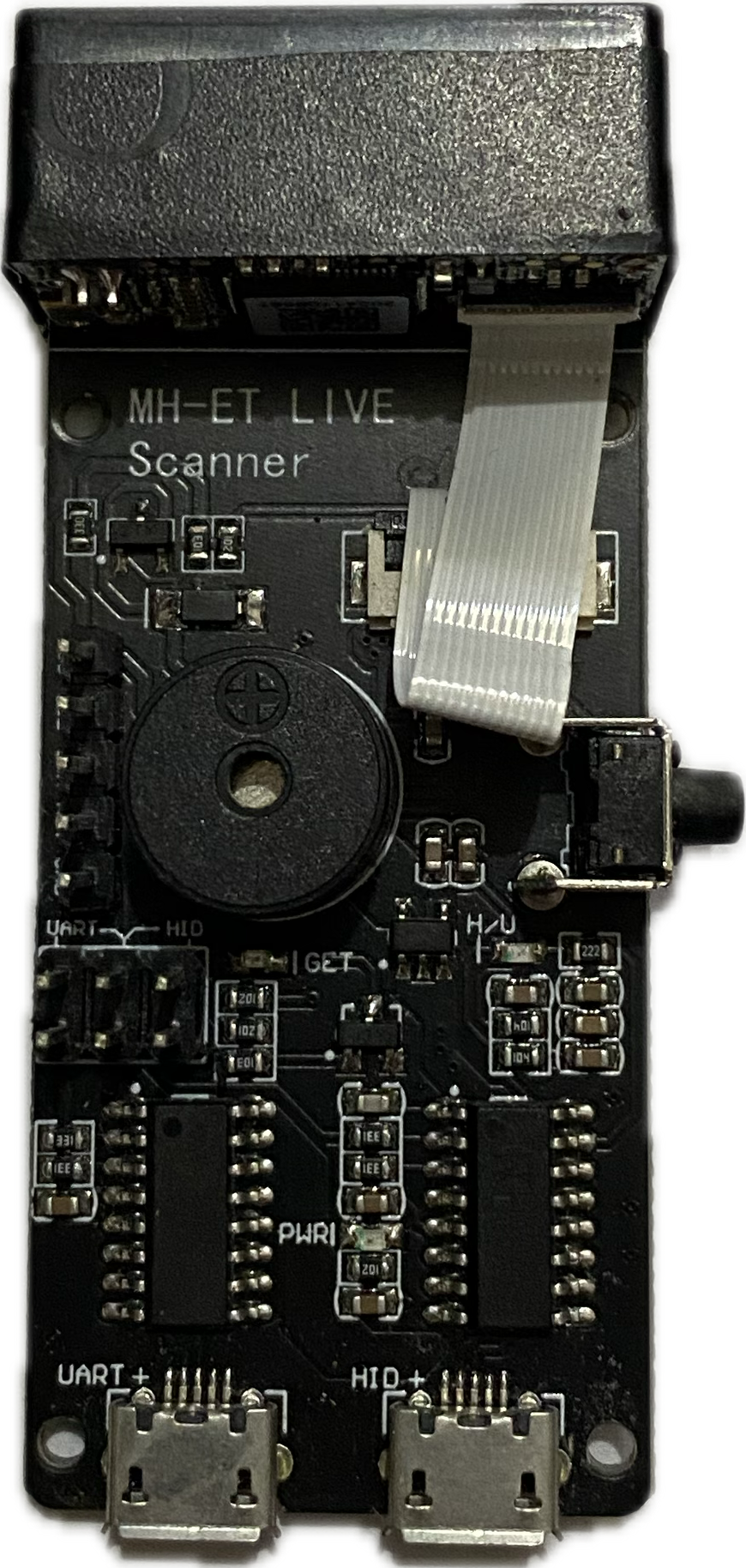
The MH-ET Live Scanner is a compact and versatile device designed for real-time monitoring and analysis of electrical signals in circuits. It is widely used for troubleshooting and diagnostics in various electronic applications. This component is particularly useful for detecting signal patterns, voltage levels, and other electrical characteristics, making it an essential tool for engineers, hobbyists, and technicians.
Explore Projects Built with MH-ET Live Scanner
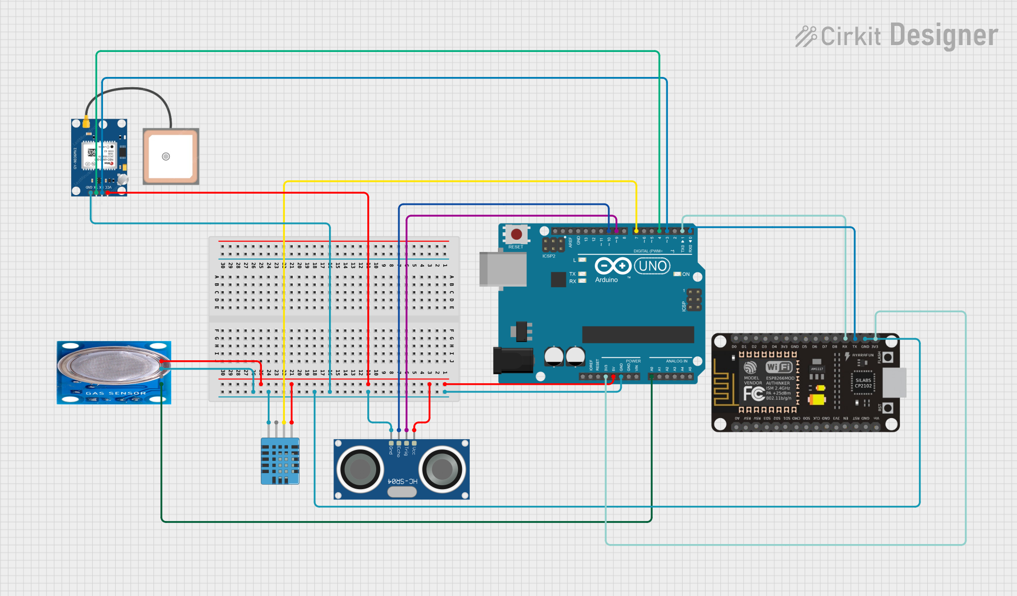
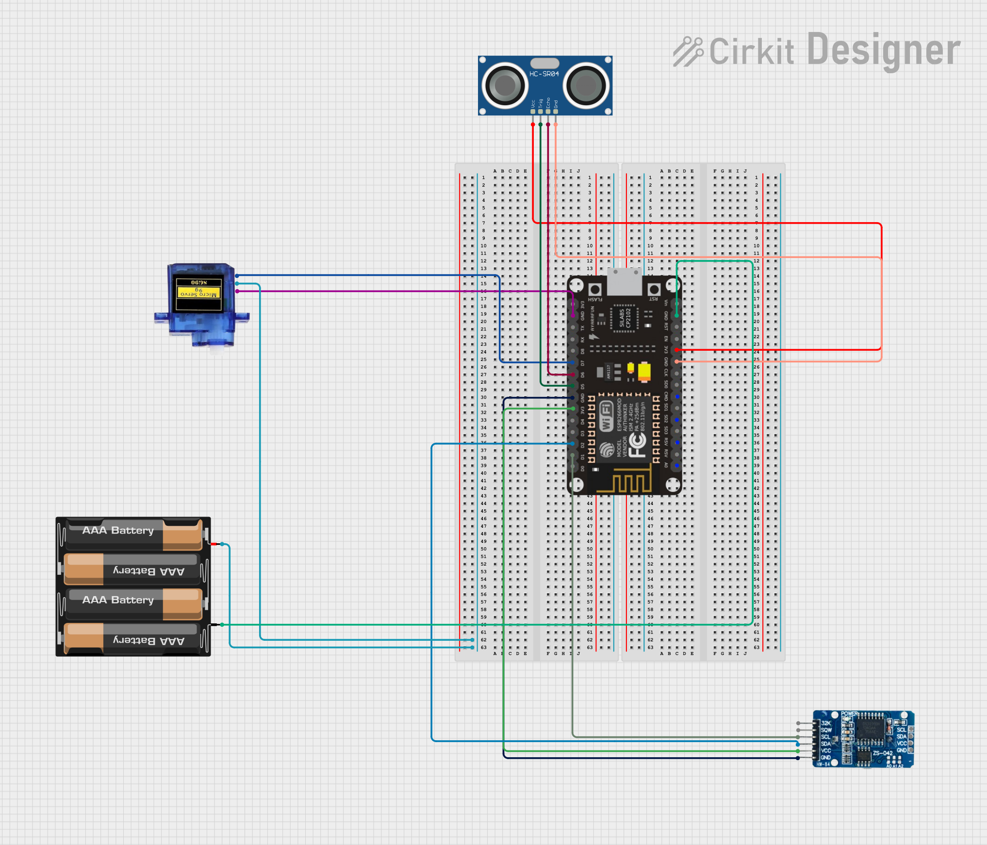
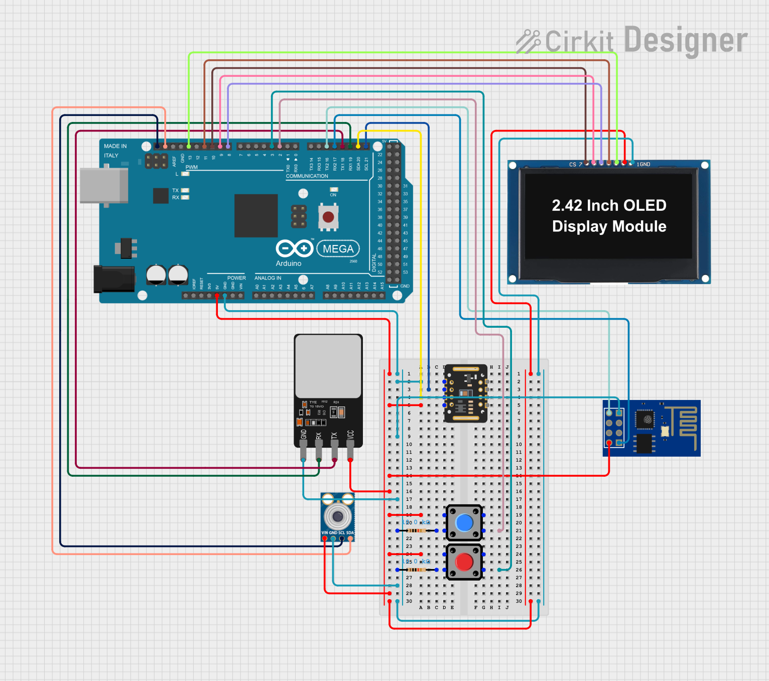
Explore Projects Built with MH-ET Live Scanner
Common Applications and Use Cases
- Debugging and troubleshooting electronic circuits
- Monitoring signal integrity in communication systems
- Analyzing voltage levels in power supply circuits
- Educational purposes for learning about signal behavior
- Testing and validating circuit designs
Technical Specifications
The MH-ET Live Scanner is designed to provide accurate and reliable signal analysis. Below are its key technical specifications:
General Specifications
| Parameter | Value |
|---|---|
| Operating Voltage | 3.3V to 5V |
| Input Signal Range | 0V to 5V |
| Display Type | LED bar graph |
| Number of LEDs | 10 |
| Response Time | Real-time |
| Dimensions | 40mm x 20mm x 10mm |
| Power Consumption | Low (<50mA) |
Pin Configuration and Descriptions
The MH-ET Live Scanner has a simple pinout for easy integration into circuits. Below is the pin configuration:
| Pin Name | Description |
|---|---|
| VCC | Power supply input (3.3V to 5V) |
| GND | Ground connection |
| SIG | Signal input for monitoring (0V to 5V range) |
Usage Instructions
The MH-ET Live Scanner is straightforward to use and can be integrated into a variety of circuits. Follow the steps below to use the component effectively:
Connecting the MH-ET Live Scanner
- Power Supply: Connect the
VCCpin to a 3.3V or 5V power source and theGNDpin to the ground of your circuit. - Signal Input: Connect the
SIGpin to the signal line you want to monitor. Ensure the signal voltage does not exceed the 0V to 5V range. - LED Display: Observe the LED bar graph, which will light up in proportion to the input signal voltage.
Important Considerations
- Signal Range: Ensure the input signal voltage is within the 0V to 5V range to avoid damaging the device.
- Power Supply: Use a stable power source to ensure accurate readings.
- Placement: Place the scanner in a location where the LEDs are easily visible for real-time monitoring.
Example: Using with Arduino UNO
The MH-ET Live Scanner can be connected to an Arduino UNO to monitor analog signals. Below is an example setup and code:
Circuit Connection
- Connect the
VCCpin of the scanner to the 5V pin on the Arduino. - Connect the
GNDpin of the scanner to the GND pin on the Arduino. - Connect the
SIGpin of the scanner to an analog output pin (e.g., A0) on the Arduino.
Arduino Code
// Example code to generate a varying signal for the MH-ET Live Scanner
// Connect the SIG pin of the scanner to pin A0 on the Arduino

void setup() {
  pinMode(A0, OUTPUT); // Set A0 as an output pin
}

void loop() {
  for (int i = 0; i <= 255; i++) {
    // Generate a ramp-up signal (0 to 5V)
    analogWrite(A0, i); // Write PWM signal to A0
    delay(10); // Small delay for smooth transition
  }
  for (int i = 255; i >= 0; i--) {
    // Generate a ramp-down signal (5V to 0)
    analogWrite(A0, i); // Write PWM signal to A0
    delay(10); // Small delay for smooth transition
  }
}
Best Practices
- Use short and well-insulated wires to minimize noise in the signal.
- Avoid exposing the scanner to high temperatures or humidity.
- Regularly check connections to ensure stable operation.
Troubleshooting and FAQs
Common Issues and Solutions
No LEDs Light Up
- Cause: Power supply not connected or insufficient voltage.
- Solution: Verify the
VCCandGNDconnections and ensure the voltage is within the 3.3V to 5V range.
LEDs Do Not Respond to Signal
- Cause: Signal voltage is out of range or not connected.
- Solution: Check the
SIGpin connection and ensure the signal voltage is between 0V and 5V.
Flickering LEDs
- Cause: Unstable power supply or noisy signal.
- Solution: Use a stable power source and add a capacitor to filter noise if necessary.
FAQs
Q: Can the MH-ET Live Scanner handle AC signals?
A: No, the scanner is designed for DC signals within the 0V to 5V range. For AC signals, use a rectifier circuit to convert them to DC.
Q: Can I use the scanner with a 12V power supply?
A: No, the maximum operating voltage is 5V. Using a higher voltage may damage the device.
Q: How do I interpret the LED bar graph?
A: The number of lit LEDs corresponds to the input signal voltage. For example, if 5 LEDs are lit, the signal voltage is approximately 2.5V.
By following this documentation, you can effectively use the MH-ET Live Scanner for real-time signal monitoring and analysis.