How to Use USB-C Breakout: Examples, Pinouts, and Specs
Introduction
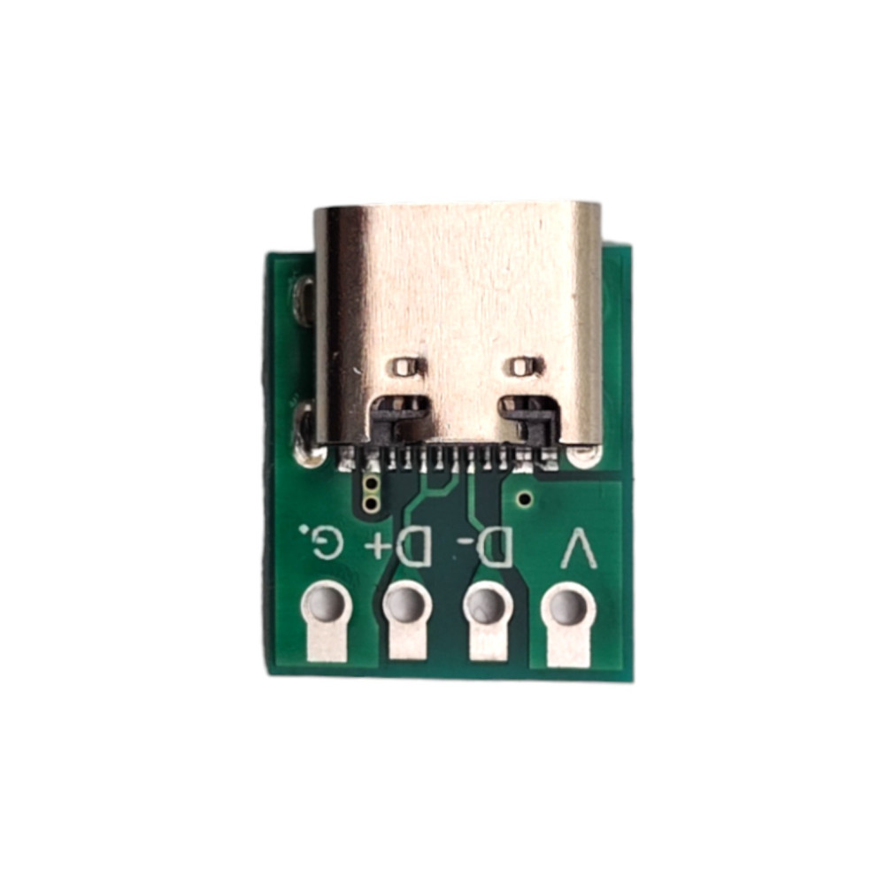
The USB-C Breakout by purecrea is a compact and versatile breakout board designed to provide easy access to the pins of a USB-C connector. This component simplifies prototyping and testing of USB-C connections by exposing the connector's pins in a user-friendly format. It is ideal for engineers, hobbyists, and developers working on USB-C-based projects, such as power delivery, data transfer, or custom USB-C peripherals.
Explore Projects Built with USB-C Breakout


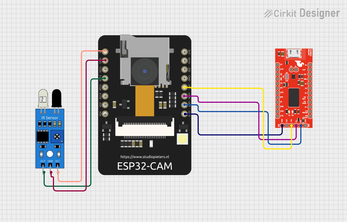
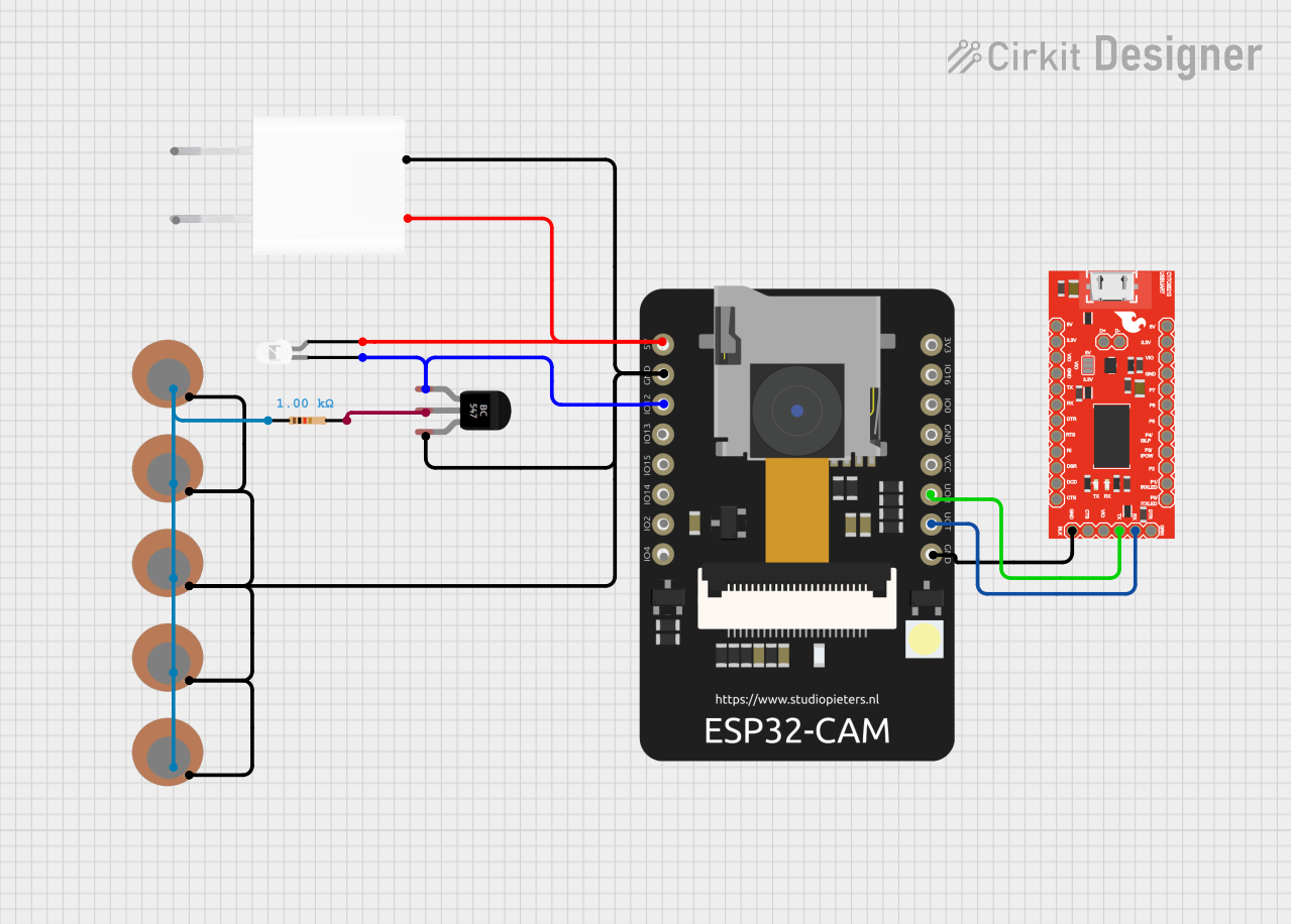
Explore Projects Built with USB-C Breakout
Common Applications and Use Cases
- Prototyping USB-C power delivery circuits
- Testing USB-C data communication protocols
- Developing custom USB-C devices or adapters
- Educational purposes for learning USB-C pinouts and functionality
- Debugging USB-C connections in existing systems
Technical Specifications
The USB-C Breakout board by purecrea is designed to meet the needs of modern USB-C applications. Below are the key technical details:
Key Specifications
- Connector Type: USB Type-C (Receptacle)
- Voltage Rating: Up to 20V (USB-C Power Delivery supported)
- Current Rating: Up to 5A (depending on the connected cable and power source)
- Pin Access: All 24 pins of the USB-C connector are broken out
- Board Dimensions: 25mm x 20mm
- Mounting Holes: 2 x M2 holes for secure mounting
- PCB Material: FR4, 1.6mm thickness
- Connector Orientation: Vertical USB-C receptacle
Pin Configuration and Descriptions
The USB-C connector has 24 pins, which are broken out on the purecrea USB-C Breakout board. The table below describes the pin configuration:
| Pin Number | Pin Name | Description |
|---|---|---|
| A1 | GND | Ground connection |
| A2 | TX1+ | SuperSpeed differential pair (positive) for data transmission |
| A3 | TX1- | SuperSpeed differential pair (negative) for data transmission |
| A4 | VBUS | Power supply input/output (5V to 20V, depending on USB-C power delivery) |
| A5 | CC1 | Configuration channel for USB-C orientation and power delivery negotiation |
| A6 | D+ | USB 2.0 differential pair (positive) for data |
| A7 | D- | USB 2.0 differential pair (negative) for data |
| A8 | SBU1 | Sideband use (used in alternate modes, e.g., DisplayPort) |
| A9 | VBUS | Power supply input/output (same as A4) |
| A10 | RX2- | SuperSpeed differential pair (negative) for data reception |
| A11 | RX2+ | SuperSpeed differential pair (positive) for data reception |
| A12 | GND | Ground connection |
| B1 | GND | Ground connection |
| B2 | TX2+ | SuperSpeed differential pair (positive) for data transmission |
| B3 | TX2- | SuperSpeed differential pair (negative) for data transmission |
| B4 | VBUS | Power supply input/output (same as A4) |
| B5 | CC2 | Configuration channel for USB-C orientation and power delivery negotiation |
| B6 | D+ | USB 2.0 differential pair (positive) for data |
| B7 | D- | USB 2.0 differential pair (negative) for data |
| B8 | SBU2 | Sideband use (used in alternate modes, e.g., DisplayPort) |
| B9 | VBUS | Power supply input/output (same as A4) |
| B10 | RX1- | SuperSpeed differential pair (negative) for data reception |
| B11 | RX1+ | SuperSpeed differential pair (positive) for data reception |
| B12 | GND | Ground connection |
Usage Instructions
How to Use the USB-C Breakout in a Circuit
- Power Supply: Connect the VBUS pin to your power source (5V to 20V, depending on your application). Ensure the power source can handle the required current (up to 5A for USB-C power delivery).
- Ground Connection: Connect the GND pins to the ground of your circuit.
- Data Lines: Use the D+ and D- pins for USB 2.0 communication or the TX/RX pairs for USB 3.0/3.1 SuperSpeed data transfer.
- Configuration Channels (CC1 and CC2): Use these pins for USB-C orientation detection and power delivery negotiation. For basic applications, connect a pull-down resistor (typically 5.1kΩ) to one of the CC pins to indicate device presence.
- Sideband Use (SBU1 and SBU2): These pins are used for alternate modes, such as DisplayPort. Ensure proper configuration if using these features.
Important Considerations and Best Practices
- Voltage and Current Limits: Do not exceed the rated voltage (20V) or current (5A) to avoid damaging the breakout board or connected devices.
- Orientation Detection: USB-C connectors are reversible. Use the CC1 and CC2 pins to detect the orientation and configure your circuit accordingly.
- Signal Integrity: Keep data lines (D+, D-, TX, RX) as short as possible to minimize signal degradation, especially for high-speed USB 3.0/3.1 communication.
- ESD Protection: Consider adding external ESD protection components to safeguard the breakout board and connected devices.
Example: Connecting to an Arduino UNO
The USB-C Breakout can be used to power an Arduino UNO or communicate with it via USB. Below is an example of powering the Arduino UNO:
// Example: Powering Arduino UNO via USB-C Breakout
// Connect the VBUS pin of the USB-C Breakout to the VIN pin of the Arduino UNO.
// Connect the GND pin of the USB-C Breakout to the GND pin of the Arduino UNO.

void setup() {
  // No specific setup required for power-only connection.
}

void loop() {
  // Your Arduino code goes here.
}
Troubleshooting and FAQs
Common Issues and Solutions
No Power Output on VBUS Pin:
- Ensure the USB-C cable is connected to a power source.
- Verify that the power source supports the required voltage and current.
- Check for proper orientation using the CC1 and CC2 pins.
Data Communication Not Working:
- Verify the connections to the D+, D-, TX, and RX pins.
- Ensure the connected device supports the desired USB protocol (e.g., USB 2.0 or USB 3.0).
- Check for signal integrity issues, such as long or improperly routed wires.
Overheating or Damage:
- Ensure the voltage and current do not exceed the rated limits (20V, 5A).
- Check for short circuits between pins.
FAQs
Q: Can I use this breakout board for USB-C Power Delivery (PD)?
A: Yes, the breakout board supports USB-C Power Delivery. However, you will need additional circuitry to negotiate the desired voltage and current levels via the CC pins.
Q: Is the breakout board compatible with alternate modes like DisplayPort?
A: Yes, the SBU1 and SBU2 pins can be used for alternate modes. Ensure proper configuration and additional circuitry as required.
Q: Can I use this breakout board to charge my phone?
A: Yes, you can use the breakout board to charge devices. Ensure the power source provides the correct voltage and current for your phone.
Q: Does the breakout board include ESD protection?
A: No, the breakout board does not include built-in ESD protection. It is recommended to add external ESD protection components for sensitive applications.