How to Use Solar Tracking System: Examples, Pinouts, and Specs
Introduction
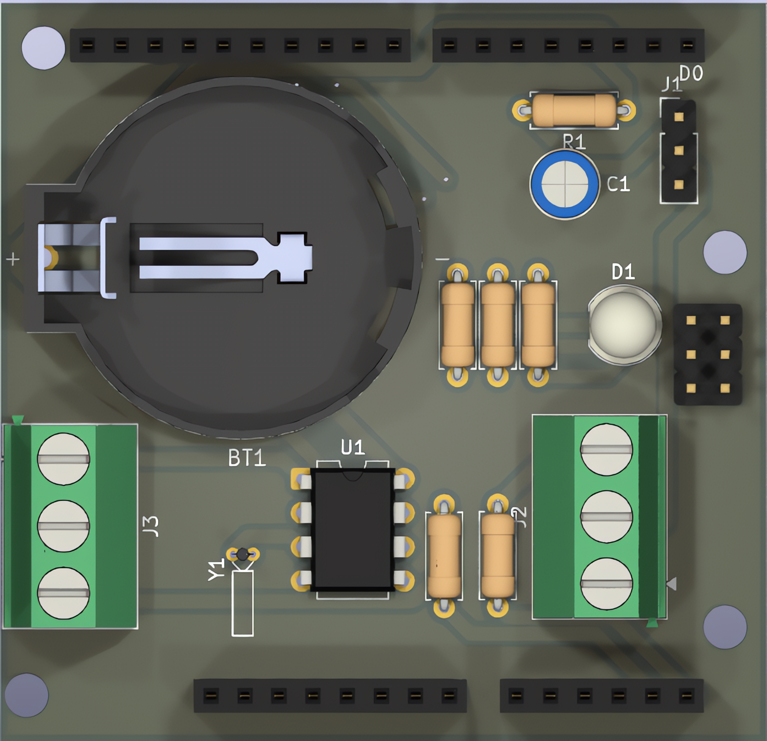
The Solar Tracking System by SYD is a device designed to optimize the energy capture of solar panels by continuously orienting them towards the sun as it moves across the sky. This system significantly improves the efficiency of solar power generation by ensuring that the panels receive maximum sunlight throughout the day.
Common applications of the Solar Tracking System include:
- Residential and commercial solar power installations
- Solar farms and large-scale renewable energy projects
- Research and development in solar energy technologies
- Portable solar power systems for off-grid applications
Explore Projects Built with Solar Tracking System
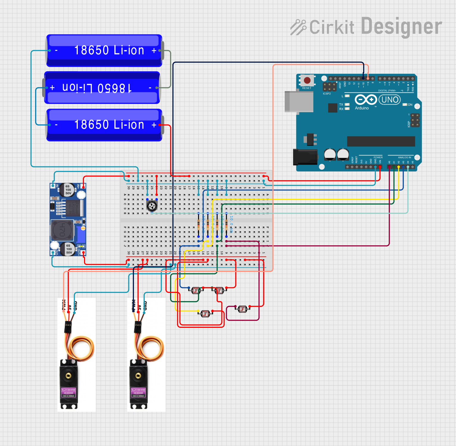
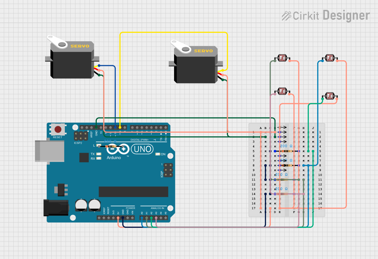

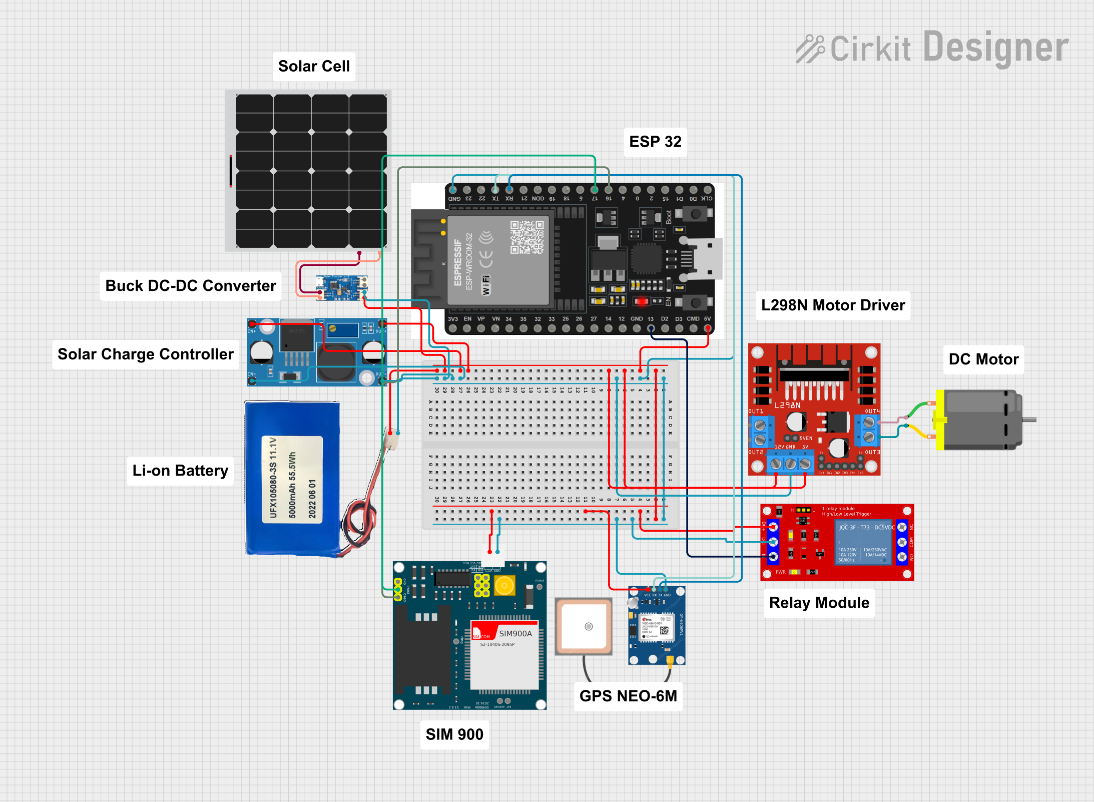
Explore Projects Built with Solar Tracking System
Technical Specifications
The following table outlines the key technical details of the SYD Solar Tracking System:
| Parameter | Specification |
|---|---|
| Operating Voltage | 12V DC |
| Power Consumption | 5W (typical) |
| Tracking Accuracy | ±2° |
| Maximum Load Capacity | 20 kg (solar panel weight) |
| Operating Temperature | -20°C to 60°C |
| Control System | Microcontroller-based (integrated) |
| Sensor Type | Light-dependent resistors (LDRs) |
| Motor Type | DC geared motor |
| Dimensions | 300mm x 200mm x 150mm |
| Weight | 2.5 kg |
Pin Configuration and Descriptions
The Solar Tracking System includes a control module with the following pin configuration:
| Pin | Name | Description |
|---|---|---|
| 1 | VCC | Power input (12V DC) |
| 2 | GND | Ground connection |
| 3 | LDR1 | Input from Light-Dependent Resistor 1 (used for sunlight detection) |
| 4 | LDR2 | Input from Light-Dependent Resistor 2 (used for sunlight detection) |
| 5 | MOTOR_A+ | Positive terminal for Motor A (horizontal movement) |
| 6 | MOTOR_A- | Negative terminal for Motor A (horizontal movement) |
| 7 | MOTOR_B+ | Positive terminal for Motor B (vertical movement) |
| 8 | MOTOR_B- | Negative terminal for Motor B (vertical movement) |
| 9 | SIGNAL_OUT | Optional signal output for external monitoring or data logging systems |
Usage Instructions
How to Use the Component in a Circuit
- Power Supply: Connect the VCC pin to a 12V DC power source and the GND pin to the ground.
- Sensor Placement: Position the LDR sensors on the solar panel frame to detect sunlight intensity from different directions.
- Motor Connections: Connect the MOTOR_A+/- and MOTOR_B+/- pins to the respective terminals of the DC motors for horizontal and vertical movement.
- Mounting: Secure the solar panel to the tracking system's frame, ensuring it is balanced and within the maximum load capacity.
- Calibration: Adjust the system's sensitivity and tracking speed using the onboard microcontroller settings (refer to the manufacturer's manual for detailed instructions).
Important Considerations and Best Practices
- Ensure the system is installed on a stable surface to prevent misalignment or damage due to wind or vibrations.
- Regularly clean the LDR sensors and solar panel surface to maintain optimal performance.
- Avoid overloading the system with panels exceeding the maximum load capacity (20 kg).
- Protect the system from water ingress if used in outdoor environments without proper weatherproofing.
Arduino UNO Integration Example
The SYD Solar Tracking System can be controlled using an Arduino UNO. Below is an example code snippet to interface with the system:
// Solar Tracking System Control with Arduino UNO
// This code adjusts the position of the solar panel based on LDR sensor readings.

#define LDR1 A0  // LDR1 connected to analog pin A0
#define LDR2 A1  // LDR2 connected to analog pin A1
#define MOTOR_A1 9  // Motor A positive terminal connected to digital pin 9
#define MOTOR_A2 10 // Motor A negative terminal connected to digital pin 10
#define MOTOR_B1 11 // Motor B positive terminal connected to digital pin 11
#define MOTOR_B2 12 // Motor B negative terminal connected to digital pin 12

void setup() {
  pinMode(LDR1, INPUT);  // Set LDR1 as input
  pinMode(LDR2, INPUT);  // Set LDR2 as input
  pinMode(MOTOR_A1, OUTPUT);  // Set Motor A1 as output
  pinMode(MOTOR_A2, OUTPUT);  // Set Motor A2 as output
  pinMode(MOTOR_B1, OUTPUT);  // Set Motor B1 as output
  pinMode(MOTOR_B2, OUTPUT);  // Set Motor B2 as output
}

void loop() {
  int ldr1Value = analogRead(LDR1);  // Read LDR1 value
  int ldr2Value = analogRead(LDR2);  // Read LDR2 value

  if (ldr1Value > ldr2Value + 50) {  // If LDR1 detects more light
    digitalWrite(MOTOR_A1, HIGH);  // Move motor A in one direction
    digitalWrite(MOTOR_A2, LOW);
  } else if (ldr2Value > ldr1Value + 50) {  // If LDR2 detects more light
    digitalWrite(MOTOR_A1, LOW);  // Move motor A in the opposite direction
    digitalWrite(MOTOR_A2, HIGH);
  } else {  // If light levels are balanced
    digitalWrite(MOTOR_A1, LOW);  // Stop motor A
    digitalWrite(MOTOR_A2, LOW);
  }

  // Add similar logic for vertical movement using MOTOR_B1 and MOTOR_B2
  delay(100);  // Small delay for stability
}
Troubleshooting and FAQs
Common Issues and Solutions
System Not Moving:
- Cause: Power supply not connected or insufficient voltage.
- Solution: Verify the power supply connection and ensure it provides 12V DC.
Inaccurate Tracking:
- Cause: Misaligned or dirty LDR sensors.
- Solution: Clean the sensors and ensure they are properly aligned.
Motor Overheating:
- Cause: Excessive load or continuous operation.
- Solution: Reduce the load on the system and allow the motors to cool periodically.
No Signal from LDRs:
- Cause: Faulty wiring or damaged sensors.
- Solution: Check the wiring and replace any damaged sensors.
FAQs
Q1: Can the system operate in cloudy weather?
A1: Yes, the system can operate in cloudy weather, but its efficiency may be reduced due to lower sunlight intensity.
Q2: Is the system compatible with other microcontrollers?
A2: Yes, the system can be integrated with other microcontrollers like Raspberry Pi or ESP32, provided the control logic is adapted.
Q3: How often should the system be maintained?
A3: Regular maintenance, such as cleaning and inspection, is recommended every 3-6 months for optimal performance.
Q4: Can the system handle multiple solar panels?
A4: The system is designed for a single panel up to 20 kg. For multiple panels, consider using additional tracking systems.