Cirkit Designer Logo
Cirkit Designer
Your all-in-one circuit design IDE
Home / 
Component Documentation

How to Use 6 axis Accelerometer and Gyroscope: Examples, Pinouts, and Specs

Image of 6 axis Accelerometer and Gyroscope
Cirkit Designer LogoDesign with 6 axis Accelerometer and Gyroscope in Cirkit Designer

Introduction

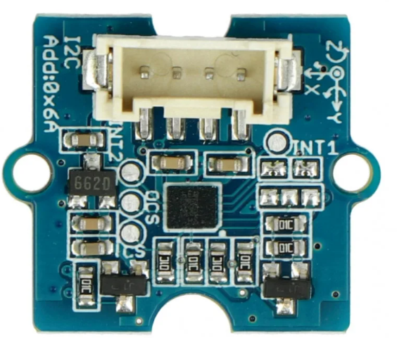
The Grove 6-Axis Accelerometer and Gyroscope is a versatile motion sensor that integrates both an accelerometer and a gyroscope into a single module. This sensor is capable of measuring acceleration and angular velocity across three axes (X, Y, and Z), making it ideal for applications requiring precise motion tracking and orientation data.

Explore Projects Built with 6 axis Accelerometer and Gyroscope

Use Cirkit Designer to design, explore, and prototype these projects online. Some projects support real-time simulation. Click "Open Project" to start designing instantly!
Arduino Nano and MPU6050 Based Gesture-Controlled Robotic Arm with Bluetooth Connectivity
Image of Copy of GLOVE ONLY FOR TOGGLE (1): A project utilizing 6 axis Accelerometer and Gyroscope in a practical application
This circuit features multiple MPU6050 accelerometer and gyroscope sensors interfaced with Arduino Nano microcontrollers, likely for capturing motion data. The Arduinos are programmed to read sensor data, calibrate input from potentiometers, and control LEDs. Communication with a Bluetooth module suggests wireless data transmission, possibly to a robotic arm or remote system, based on the motion and flex sensor inputs.
Cirkit Designer LogoOpen Project in Cirkit Designer
Arduino UNO and MPU6050 Accelerometer-Gyroscope Sensor for Motion Tracking
Image of MPU-6050 sensor: A project utilizing 6 axis Accelerometer and Gyroscope in a practical application
This circuit consists of an Arduino UNO microcontroller connected to an MPU6050 accelerometer and gyroscope sensor. The Arduino reads acceleration and gyroscopic data from the MPU6050 via the I2C interface and outputs the sensor readings to the serial monitor.
Cirkit Designer LogoOpen Project in Cirkit Designer
Arduino UNO and MPU-6050 Based Motion Sensing System with I2C Interface
Image of mpu6050new: A project utilizing 6 axis Accelerometer and Gyroscope in a practical application
This circuit features an Arduino UNO connected to an MPU-6050 accelerometer and gyroscope sensor via an I2C module. The Arduino UNO provides power to the sensor and communicates with it using the I2C protocol, enabling the collection of motion and orientation data.
Cirkit Designer LogoOpen Project in Cirkit Designer
Raspberry Pi 5-Based Multi-Sensor IMU System with MPU-6050 and LSM303c
Image of GRS: A project utilizing 6 axis Accelerometer and Gyroscope in a practical application
This circuit integrates a Raspberry Pi 5 with multiple sensors, including an MPU-6050 accelerometer and gyroscope, and an LSM303c 6DOF IMU, to collect and process motion and orientation data. The Raspberry Pi serves as the central processing unit, interfacing with the sensors via GPIO pins and providing power to them.
Cirkit Designer LogoOpen Project in Cirkit Designer

Explore Projects Built with 6 axis Accelerometer and Gyroscope

Use Cirkit Designer to design, explore, and prototype these projects online. Some projects support real-time simulation. Click "Open Project" to start designing instantly!
Image of Copy of GLOVE ONLY FOR TOGGLE (1): A project utilizing 6 axis Accelerometer and Gyroscope in a practical application
Arduino Nano and MPU6050 Based Gesture-Controlled Robotic Arm with Bluetooth Connectivity
This circuit features multiple MPU6050 accelerometer and gyroscope sensors interfaced with Arduino Nano microcontrollers, likely for capturing motion data. The Arduinos are programmed to read sensor data, calibrate input from potentiometers, and control LEDs. Communication with a Bluetooth module suggests wireless data transmission, possibly to a robotic arm or remote system, based on the motion and flex sensor inputs.
Cirkit Designer LogoOpen Project in Cirkit Designer
Image of MPU-6050 sensor: A project utilizing 6 axis Accelerometer and Gyroscope in a practical application
Arduino UNO and MPU6050 Accelerometer-Gyroscope Sensor for Motion Tracking
This circuit consists of an Arduino UNO microcontroller connected to an MPU6050 accelerometer and gyroscope sensor. The Arduino reads acceleration and gyroscopic data from the MPU6050 via the I2C interface and outputs the sensor readings to the serial monitor.
Cirkit Designer LogoOpen Project in Cirkit Designer
Image of mpu6050new: A project utilizing 6 axis Accelerometer and Gyroscope in a practical application
Arduino UNO and MPU-6050 Based Motion Sensing System with I2C Interface
This circuit features an Arduino UNO connected to an MPU-6050 accelerometer and gyroscope sensor via an I2C module. The Arduino UNO provides power to the sensor and communicates with it using the I2C protocol, enabling the collection of motion and orientation data.
Cirkit Designer LogoOpen Project in Cirkit Designer
Image of GRS: A project utilizing 6 axis Accelerometer and Gyroscope in a practical application
Raspberry Pi 5-Based Multi-Sensor IMU System with MPU-6050 and LSM303c
This circuit integrates a Raspberry Pi 5 with multiple sensors, including an MPU-6050 accelerometer and gyroscope, and an LSM303c 6DOF IMU, to collect and process motion and orientation data. The Raspberry Pi serves as the central processing unit, interfacing with the sensors via GPIO pins and providing power to them.
Cirkit Designer LogoOpen Project in Cirkit Designer

Common Applications

  • Robotics and drone navigation
  • Gesture recognition
  • Gaming and virtual reality systems
  • Fitness and health tracking devices
  • Industrial equipment monitoring

Technical Specifications

The following table outlines the key technical details of the Grove 6-Axis Accelerometer and Gyroscope:

Parameter Value
Operating Voltage 3.3V / 5V
Communication Protocol I2C
Accelerometer Range ±2g, ±4g, ±8g, ±16g
Gyroscope Range ±250°/s, ±500°/s, ±1000°/s, ±2000°/s
Operating Temperature -40°C to +85°C
Dimensions 20mm x 40mm

Pin Configuration

The Grove 6-Axis Accelerometer and Gyroscope module has a standard Grove connector with the following pinout:

Pin Name Description
1 VCC Power supply (3.3V or 5V)
2 GND Ground
3 SDA I2C data line
4 SCL I2C clock line

Usage Instructions

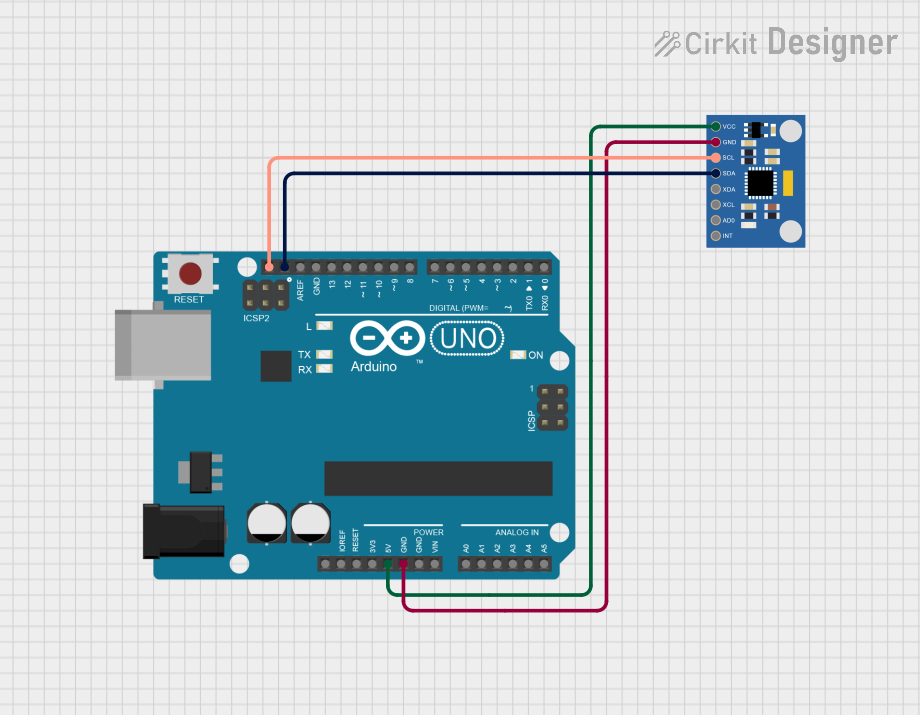
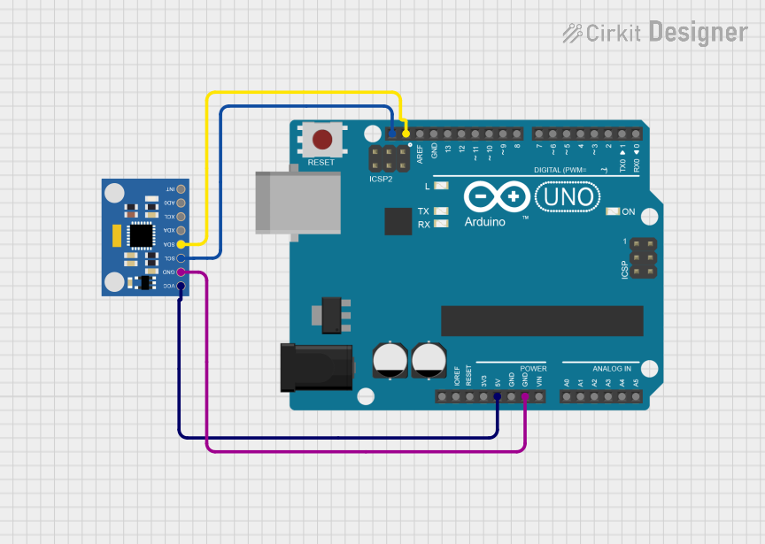
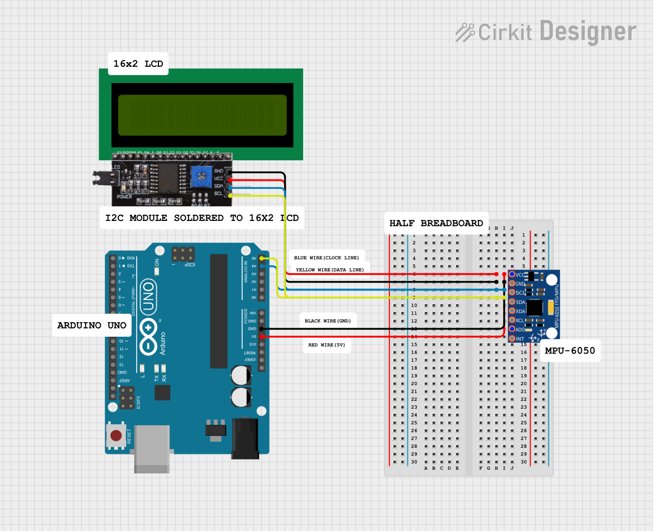
Connecting the Sensor

  1. Hardware Setup:

    • Connect the Grove 6-Axis Accelerometer and Gyroscope to an I2C port on a Grove Base Shield.
    • Attach the Base Shield to an Arduino UNO or compatible microcontroller.
    • Ensure the power supply matches the sensor's operating voltage (3.3V or 5V).
  2. Software Setup:

    • Install the required library for the sensor. For example, if the sensor uses the MPU6050 chip, install the MPU6050 library from the Arduino Library Manager.

Sample Arduino Code

Below is an example code to read acceleration and gyroscope data from the sensor:

#include <Wire.h>
#include <MPU6050.h> // Include the MPU6050 library

MPU6050 mpu; // Create an MPU6050 object

void setup() {
  Serial.begin(9600); // Initialize serial communication
  Wire.begin();       // Initialize I2C communication

  // Initialize the MPU6050 sensor
  if (!mpu.begin(MPU6050_SCALE_2000DPS, MPU6050_RANGE_16G)) {
    Serial.println("Could not find a valid MPU6050 sensor, check connections!");
    while (1);
  }

  Serial.println("MPU6050 initialized successfully!");
}

void loop() {
  // Read acceleration and gyroscope data
  Vector rawAccel = mpu.readRawAccel();
  Vector rawGyro = mpu.readRawGyro();

  // Print acceleration data
  Serial.print("Accel X: "); Serial.print(rawAccel.XAxis);
  Serial.print(" | Accel Y: "); Serial.print(rawAccel.YAxis);
  Serial.print(" | Accel Z: "); Serial.println(rawAccel.ZAxis);

  // Print gyroscope data
  Serial.print("Gyro X: "); Serial.print(rawGyro.XAxis);
  Serial.print(" | Gyro Y: "); Serial.print(rawGyro.YAxis);
  Serial.print(" | Gyro Z: "); Serial.println(rawGyro.ZAxis);

  delay(500); // Delay for readability
}

Important Considerations

  • Power Supply: Ensure the sensor is powered with the correct voltage (3.3V or 5V).
  • I2C Address: The default I2C address for the sensor may vary. Check the datasheet or library documentation for the correct address.
  • Mounting Orientation: Properly align the sensor to ensure accurate motion tracking.

Troubleshooting and FAQs

Common Issues

  1. No Data Output:

    • Cause: Incorrect wiring or loose connections.
    • Solution: Verify the connections between the sensor and the microcontroller.
  2. Incorrect Readings:

    • Cause: Improper sensor calibration.
    • Solution: Use the library's calibration functions to calibrate the sensor.
  3. I2C Communication Failure:

    • Cause: Address conflict or incorrect I2C address.
    • Solution: Check the sensor's I2C address and ensure no other devices on the bus share the same address.

FAQs

Q: Can this sensor be used with a Raspberry Pi?
A: Yes, the sensor can be used with a Raspberry Pi via the I2C interface. Ensure the appropriate libraries are installed.

Q: How do I change the sensor's sensitivity range?
A: The sensitivity range can be configured in the library's initialization function. Refer to the library documentation for details.

Q: Is the sensor affected by temperature changes?
A: The sensor has a built-in temperature compensation mechanism, but extreme temperature variations may still affect accuracy.