Cirkit Designer Logo
Cirkit Designer
Your all-in-one circuit design IDE
Home / 
Component Documentation

How to Use Adafruit Gear-Reduced Stepper Motor (small): Examples, Pinouts, and Specs

Image of Adafruit Gear-Reduced Stepper Motor (small)
Cirkit Designer LogoDesign with Adafruit Gear-Reduced Stepper Motor (small) in Cirkit Designer

Introduction

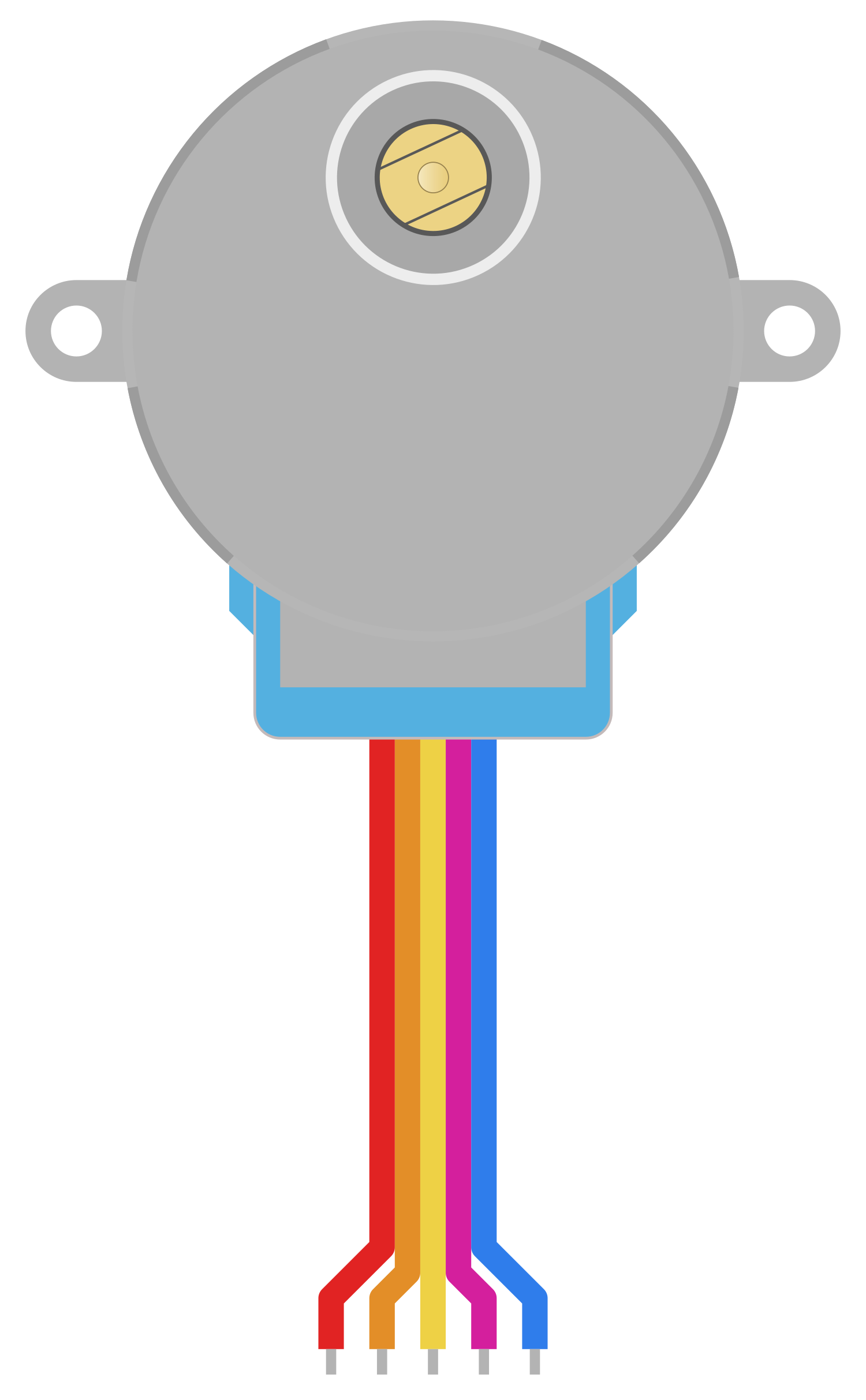
The Adafruit Gear-Reduced Stepper Motor is a compact and robust stepper motor equipped with a gear reduction mechanism. This motor is designed to offer precise control over rotational motion, making it an ideal choice for applications in robotics, 3D printers, CNC machines, and other projects that require accurate positioning and motion control. The gear reduction increases the torque output and provides finer control over the motor's position, which is essential for tasks that demand high precision.

Explore Projects Built with Adafruit Gear-Reduced Stepper Motor (small)

Use Cirkit Designer to design, explore, and prototype these projects online. Some projects support real-time simulation. Click "Open Project" to start designing instantly!
Arduino-Controlled Stepper Motor with ULN2003A Driver
Image of TAGLE 4.: A project utilizing Adafruit Gear-Reduced Stepper Motor (small) in a practical application
This circuit controls a gear-reduced stepper motor using an Arduino UNO and a ULN2003A breakout board. The Arduino UNO is programmed to drive the stepper motor with a specific number of steps in response to serial input commands, allowing for precise motor control. The ULN2003A interfaces between the low-power Arduino outputs and the higher-power requirements of the stepper motor.
Cirkit Designer LogoOpen Project in Cirkit Designer
Arduino-Controlled Stepper Motor with Sound Sensing and Variable Speed
Image of Case Study: A project utilizing Adafruit Gear-Reduced Stepper Motor (small) in a practical application
This circuit features an Arduino UNO microcontroller interfaced with a sound sensor, a potentiometer, and a gear-reduced stepper motor. The sound sensor and potentiometer provide analog inputs to the Arduino, which processes these signals to adjust the speed of the stepper motor based on the computed risk factor and potentiometer value. The stepper motor's rotation speed is dynamically controlled through the Arduino's digital pins, responding to environmental sound levels and manual adjustments from the potentiometer.
Cirkit Designer LogoOpen Project in Cirkit Designer
Arduino UNO Controlled Stepper Motor with Force Sensing and Vibration Feedback
Image of glove: A project utilizing Adafruit Gear-Reduced Stepper Motor (small) in a practical application
This circuit uses an Arduino UNO to control a stepper motor via a ULN 2003 driver and a vibration motor. It also includes two force-sensing resistors for input, with their signals conditioned by resistors before being read by the Arduino.
Cirkit Designer LogoOpen Project in Cirkit Designer
Arduino UNO Controlled Stepper Motor with LED Indicators
Image of RFID #6: A project utilizing Adafruit Gear-Reduced Stepper Motor (small) in a practical application
This circuit uses an Arduino UNO to control a stepper motor via a ULN2003A breakout board and three LEDs (red, green, and yellow) with current-limiting resistors. The Arduino provides power and control signals to the motor driver and LEDs, enabling motor movement and LED indication.
Cirkit Designer LogoOpen Project in Cirkit Designer

Explore Projects Built with Adafruit Gear-Reduced Stepper Motor (small)

Use Cirkit Designer to design, explore, and prototype these projects online. Some projects support real-time simulation. Click "Open Project" to start designing instantly!
Image of TAGLE 4.: A project utilizing Adafruit Gear-Reduced Stepper Motor (small) in a practical application
Arduino-Controlled Stepper Motor with ULN2003A Driver
This circuit controls a gear-reduced stepper motor using an Arduino UNO and a ULN2003A breakout board. The Arduino UNO is programmed to drive the stepper motor with a specific number of steps in response to serial input commands, allowing for precise motor control. The ULN2003A interfaces between the low-power Arduino outputs and the higher-power requirements of the stepper motor.
Cirkit Designer LogoOpen Project in Cirkit Designer
Image of Case Study: A project utilizing Adafruit Gear-Reduced Stepper Motor (small) in a practical application
Arduino-Controlled Stepper Motor with Sound Sensing and Variable Speed
This circuit features an Arduino UNO microcontroller interfaced with a sound sensor, a potentiometer, and a gear-reduced stepper motor. The sound sensor and potentiometer provide analog inputs to the Arduino, which processes these signals to adjust the speed of the stepper motor based on the computed risk factor and potentiometer value. The stepper motor's rotation speed is dynamically controlled through the Arduino's digital pins, responding to environmental sound levels and manual adjustments from the potentiometer.
Cirkit Designer LogoOpen Project in Cirkit Designer
Image of glove: A project utilizing Adafruit Gear-Reduced Stepper Motor (small) in a practical application
Arduino UNO Controlled Stepper Motor with Force Sensing and Vibration Feedback
This circuit uses an Arduino UNO to control a stepper motor via a ULN 2003 driver and a vibration motor. It also includes two force-sensing resistors for input, with their signals conditioned by resistors before being read by the Arduino.
Cirkit Designer LogoOpen Project in Cirkit Designer
Image of RFID #6: A project utilizing Adafruit Gear-Reduced Stepper Motor (small) in a practical application
Arduino UNO Controlled Stepper Motor with LED Indicators
This circuit uses an Arduino UNO to control a stepper motor via a ULN2003A breakout board and three LEDs (red, green, and yellow) with current-limiting resistors. The Arduino provides power and control signals to the motor driver and LEDs, enabling motor movement and LED indication.
Cirkit Designer LogoOpen Project in Cirkit Designer

Technical Specifications

Key Technical Details

  • Motor Type: Bipolar Stepper
  • Gear Ratio: Typically around 1:64 reduction
  • Step Angle: 5.625°/64 (due to gear reduction)
  • Voltage Rating: 5-12V DC
  • Current Rating: Varies with voltage (see datasheet for details)
  • Holding Torque: Specified in N·m (Newton-meters) in the datasheet
  • Number of Leads: 4
  • Shaft Diameter: Typically 5mm

Pin Configuration and Descriptions

Pin Number Description Color (Common)
1 Coil A1 Red
2 Coil A2 Yellow
3 Coil B1 Green
4 Coil B2 Blue

Note: Always refer to the manufacturer's datasheet for the most accurate pinout and color coding.

Usage Instructions

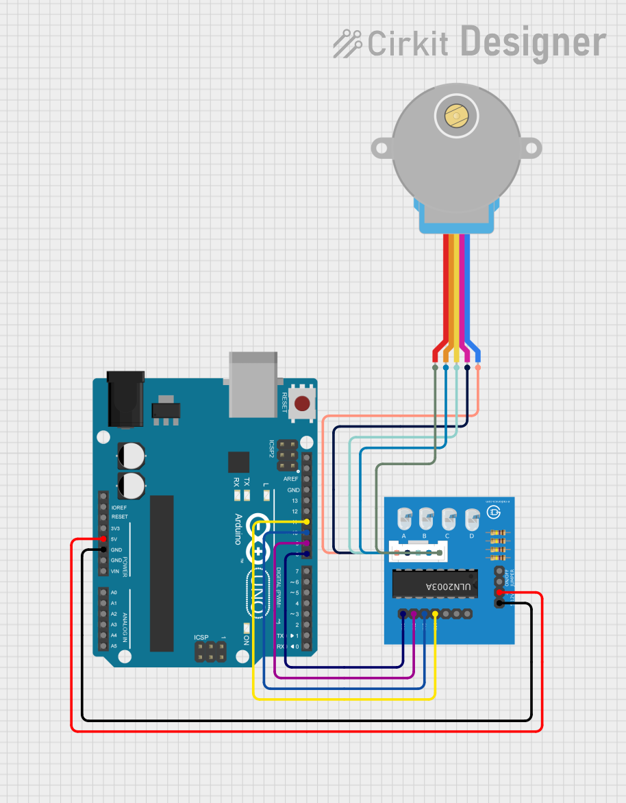
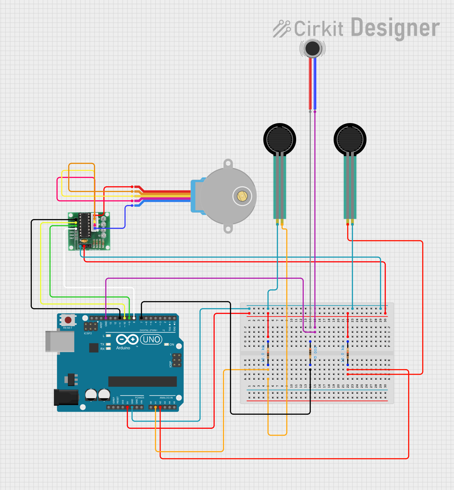
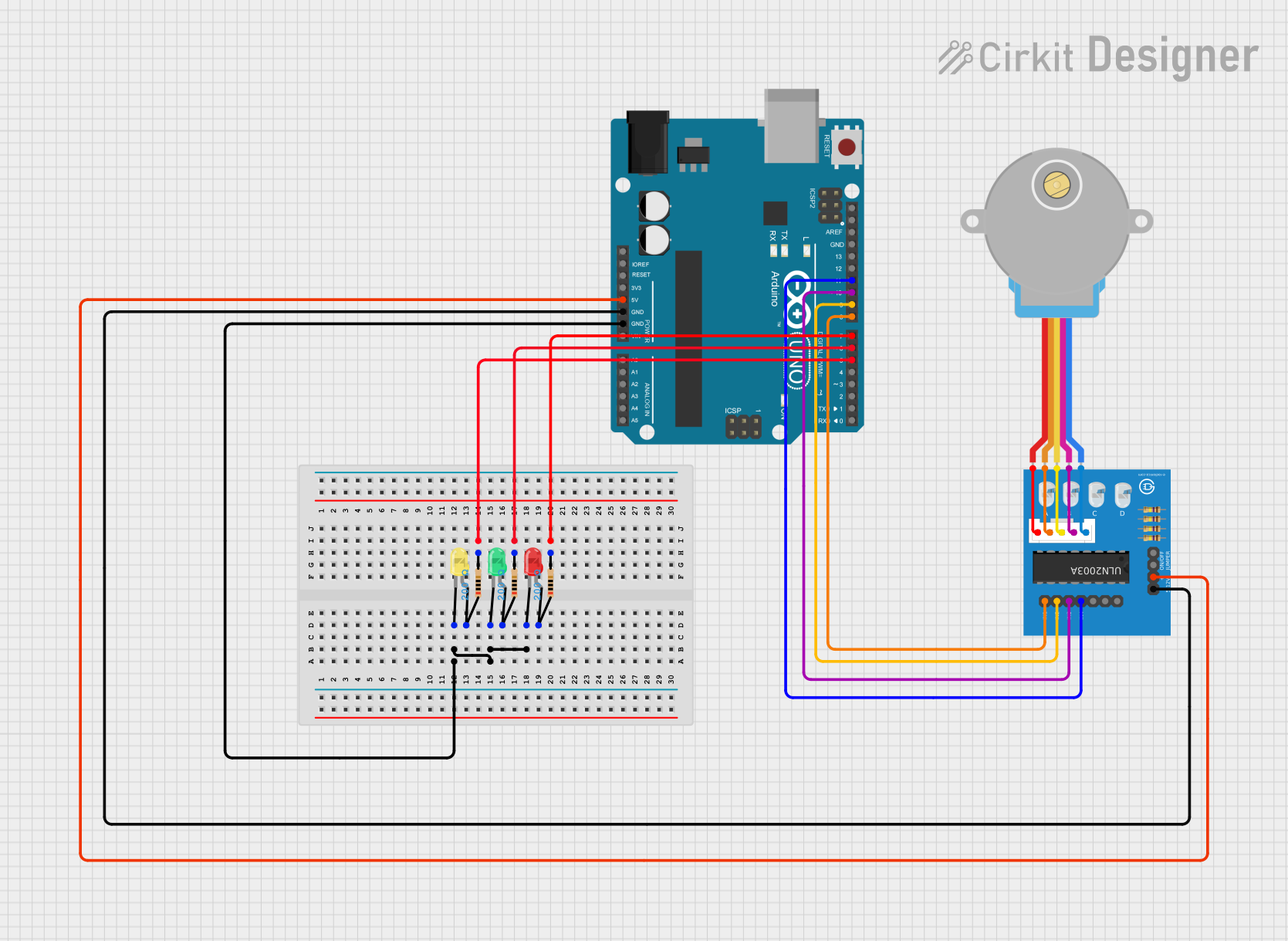
Connecting to a Circuit

To use the Adafruit Gear-Reduced Stepper Motor with an Arduino UNO, you will need a stepper motor driver, such as the Adafruit Motor/Stepper/Servo Shield or a dedicated driver like the A4988. The driver is necessary to control the current in each coil and to protect the Arduino from the high current that the motor can draw.

  1. Connect the motor's leads to the motor driver according to the driver's pinout.
  2. Connect the motor driver to the Arduino UNO by following the driver's wiring diagram.
  3. Supply the motor driver with an appropriate external power source (5-12V DC) for the motor.

Important Considerations and Best Practices

  • Do not connect the motor directly to the Arduino pins, as this can damage the board.
  • Use an external power supply to provide sufficient current for the motor.
  • Ensure that the motor driver is compatible with the motor's voltage and current requirements.
  • Always double-check wiring before powering up the system to prevent damage.

Example Arduino Code

#include <Stepper.h>

// Change these values based on your motor's specifications
const int stepsPerRevolution = 2048; // steps per revolution (5.625°/64)
const int motorSpeed = 60; // RPM (revolutions per minute)

// Initialize the stepper library on pins 8 through 11:
Stepper myStepper(stepsPerRevolution, 8, 10, 9, 11);

void setup() {
  // Set the motor speed (RPM):
  myStepper.setSpeed(motorSpeed);
  // Begin Serial communication for debugging:
  Serial.begin(9600);
}

void loop() {
  // Step one revolution in one direction:
  Serial.println("Clockwise");
  myStepper.step(stepsPerRevolution);
  delay(500);

  // Step one revolution in the other direction:
  Serial.println("Counterclockwise");
  myStepper.step(-stepsPerRevolution);
  delay(500);
}

Note: The pin numbers (8, 10, 9, 11) are placeholders and should be replaced with the actual pins used to connect the motor driver to the Arduino.

Troubleshooting and FAQs

Common Issues

  • Motor does not turn: Check the wiring and ensure that the motor driver is properly connected and configured.
  • Motor stalls or misses steps: This could be due to insufficient current or voltage. Check the power supply and adjust the driver settings.
  • Motor overheats: Ensure that the current settings on the motor driver are not too high for the motor.

Solutions and Tips for Troubleshooting

  • Double-check all connections and ensure they are secure.
  • Refer to the motor driver's documentation for proper configuration and current settings.
  • Use a multimeter to verify the voltage at the motor and the current draw.
  • If using a shield or module, ensure that it is seated correctly on the Arduino.

FAQs

Q: Can I run this motor at a higher voltage than rated? A: Running the motor at a higher voltage than specified can lead to overheating and damage. Always adhere to the manufacturer's specifications.

Q: How do I reverse the direction of the motor? A: To reverse the direction, you can reverse the sequence of control signals to the motor or simply call the step() function with a negative number of steps.

Q: What is the maximum speed of the motor? A: The maximum speed depends on the voltage and the load on the motor. Check the datasheet for the maximum rated speed, and ensure that your application does not exceed this limit.

Note: This documentation is for informational purposes only. Always consult the manufacturer's datasheet and resources for the most accurate and detailed information on your specific motor model.