
How to Use Y180: Examples, Pinouts, and Specs
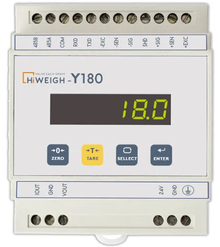
 Design with Y180 in Cirkit Designer
Introduction
The Y180, manufactured by Hiweigh (Part ID: 180), is a high-performance operational amplifier (op-amp) designed for applications requiring low noise and high speed. Its robust design and precision make it ideal for audio processing, signal amplification, and instrumentation systems. The Y180 is widely used in professional audio equipment, medical devices, and high-frequency signal processing circuits.
Explore Projects Built with Y180
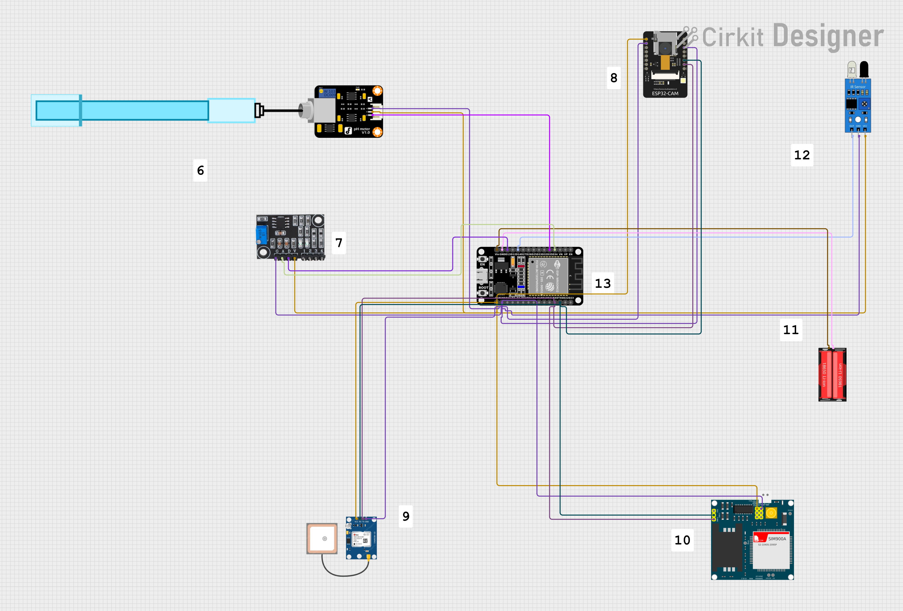 Open Project in Cirkit Designer
 Open Project in Cirkit Designer
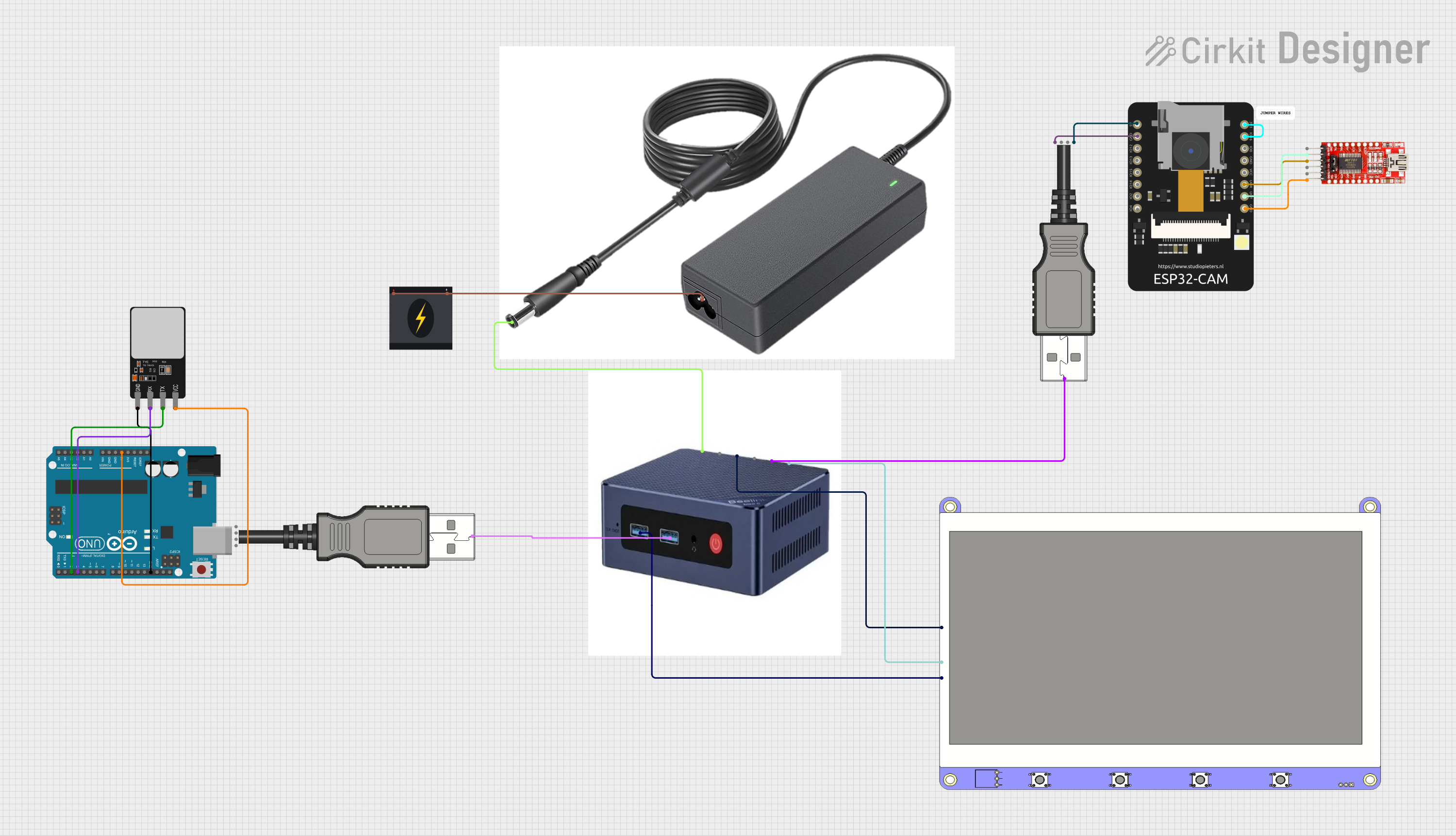 Open Project in Cirkit Designer
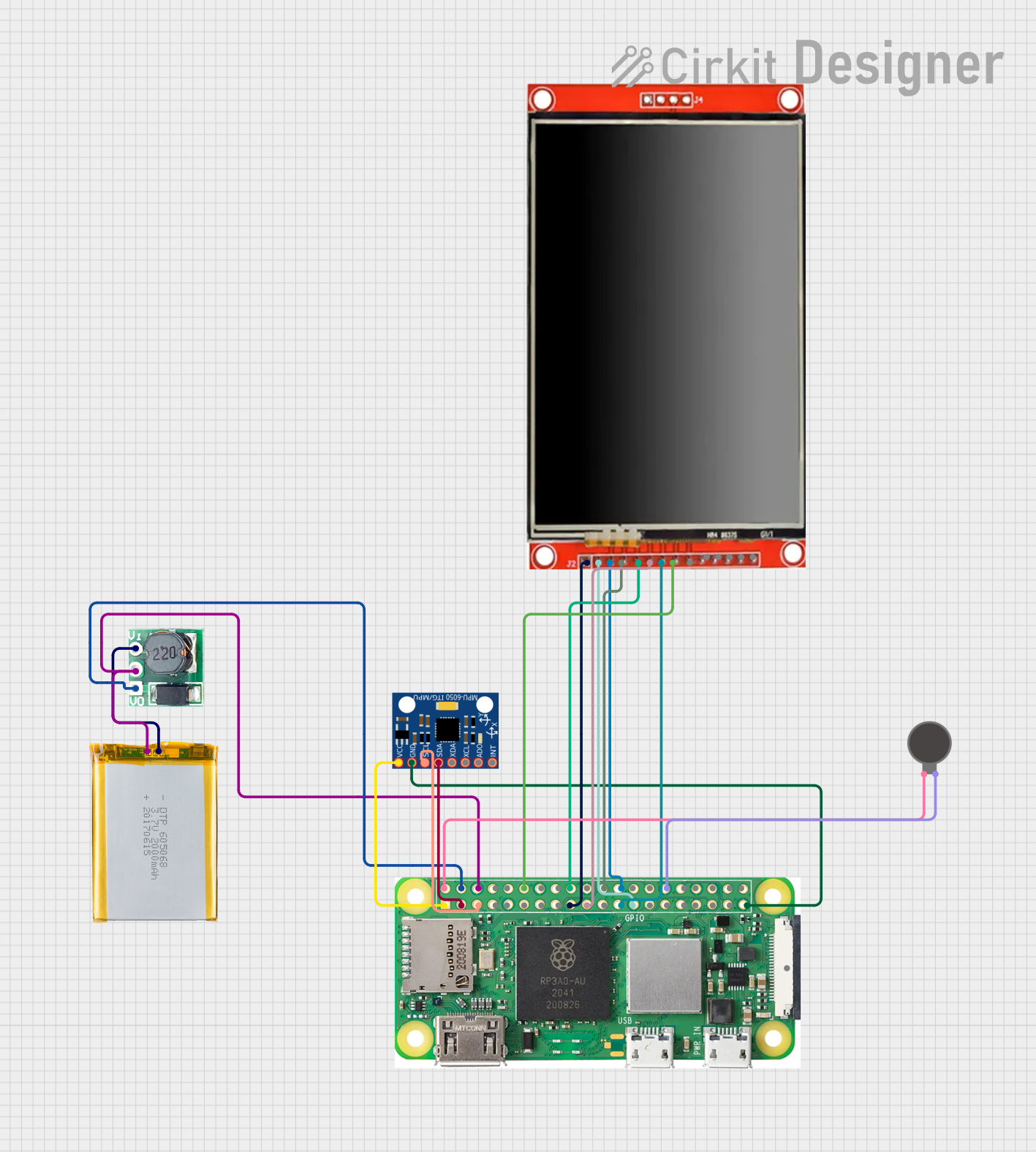 Open Project in Cirkit Designer
Explore Projects Built with Y180
Open Project in Cirkit DesignerOpen Project in Cirkit DesignerOpen Project in Cirkit DesignerOpen Project in Cirkit DesignerCommon Applications
- Audio signal amplification
- Active filters and equalizers
- Medical instrumentation (e.g., ECG, EEG amplifiers)
- High-speed data acquisition systems
- Precision measurement and control systems
Technical Specifications
The Y180 op-amp is engineered to deliver exceptional performance in demanding environments. Below are its key technical specifications:
| Parameter | Value |
|---|---|
| Supply Voltage Range | ±5V to ±18V |
| Input Offset Voltage | 0.5 mV (typical) |
| Input Bias Current | 10 nA (typical) |
| Gain Bandwidth Product | 20 MHz |
| Slew Rate | 15 V/µs |
| Noise Density | 2.5 nV/√Hz @ 1 kHz |
| Output Voltage Swing | ±14V (with ±15V supply) |
| Operating Temperature | -40°C to +85°C |
| Package Type | 8-pin DIP, SOIC |
Pin Configuration and Descriptions
The Y180 is available in an 8-pin package. The pinout and descriptions are as follows:
| Pin Number | Pin Name | Description |
|---|---|---|
| 1 | Offset Null | Offset voltage adjustment (input 1) |
| 2 | Inverting Input (-) | Inverting input terminal |
| 3 | Non-Inverting Input (+) | Non-inverting input terminal |
| 4 | V- (Negative Supply) | Negative power supply |
| 5 | Offset Null | Offset voltage adjustment (input 2) |
| 6 | Output | Output terminal |
| 7 | V+ (Positive Supply) | Positive power supply |
| 8 | NC (No Connect) | Not connected internally |
Usage Instructions
How to Use the Y180 in a Circuit
- Power Supply: Connect the Y180 to a dual power supply (e.g., ±15V) for optimal performance. Ensure the supply voltage does not exceed the specified range (±18V).
- Input Connections:
- Connect the signal source to the non-inverting (+) or inverting (-) input, depending on the desired configuration (e.g., inverting or non-inverting amplifier).
- Use appropriate resistors and capacitors to set the gain and bandwidth.
- Output Load: Ensure the load connected to the output does not exceed the op-amp's drive capability.
- Offset Adjustment: If required, use the offset null pins (1 and 5) to minimize input offset voltage.
Important Considerations
- Decoupling Capacitors: Place decoupling capacitors (e.g., 0.1 µF ceramic and 10 µF electrolytic) close to the power supply pins to reduce noise and improve stability.
- Thermal Management: Ensure adequate ventilation or heat dissipation if the op-amp operates in high-power applications.
- PCB Layout: Use a clean and low-noise PCB layout. Keep input traces short and away from high-frequency or high-current paths.
Example: Using the Y180 with an Arduino UNO
The Y180 can be used to amplify analog signals for an Arduino UNO. Below is an example of a non-inverting amplifier circuit with a gain of 10.
Circuit Setup
- Connect the Y180's non-inverting input (+) to the signal source.
- Use a resistor divider network to set the gain (e.g., R1 = 1 kΩ, R2 = 9 kΩ).
- Connect the output of the Y180 to an analog input pin on the Arduino UNO.
Arduino Code
// Example code to read amplified signal from Y180 and display it via Serial Monitor

const int analogPin = A0; // Analog pin connected to Y180 output
int sensorValue = 0;      // Variable to store the analog reading

void setup() {
  Serial.begin(9600); // Initialize serial communication at 9600 baud
}

void loop() {
  sensorValue = analogRead(analogPin); // Read the analog value
  float voltage = sensorValue * (5.0 / 1023.0); // Convert to voltage
  Serial.print("Amplified Voltage: ");
  Serial.print(voltage);
  Serial.println(" V");
  delay(500); // Wait for 500 ms before the next reading
}
Troubleshooting and FAQs
Common Issues
No Output Signal:
- Check the power supply connections and ensure the voltage is within the specified range.
- Verify that the input signal is properly connected and within the op-amp's input range.
- Inspect the circuit for loose connections or damaged components.
Distorted Output:
- Ensure the load impedance is not too low for the op-amp to drive.
- Check for excessive input signal levels that may cause clipping.
- Verify that the gain-setting resistors are correctly calculated and installed.
High Noise Levels:
- Use proper decoupling capacitors near the power supply pins.
- Minimize the length of input and output traces to reduce noise pickup.
- Shield the circuit from external electromagnetic interference (EMI).
FAQs
Q1: Can the Y180 operate with a single power supply?
A1: Yes, the Y180 can operate with a single supply, but the input and output signals must be biased appropriately to stay within the op-amp's operating range.
Q2: What is the maximum gain I can achieve with the Y180?
A2: The maximum gain depends on the application and bandwidth requirements. For high-frequency signals, the gain-bandwidth product (20 MHz) limits the achievable gain.
Q3: Is the Y180 suitable for battery-powered applications?
A3: Yes, the Y180's low power consumption and wide supply voltage range make it suitable for battery-powered devices.
Q4: How do I adjust the offset voltage?
A4: Use a 10 kΩ potentiometer connected between the offset null pins (1 and 5) and the negative supply (V-) to fine-tune the offset voltage.
By following this documentation, users can effectively integrate the Y180 into their projects and troubleshoot common issues with ease.