How to Use 12V to 5V Regulator: Examples, Pinouts, and Specs
Introduction
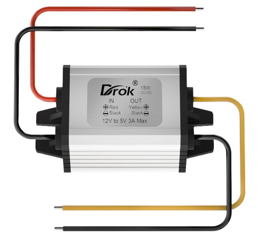
A 12V to 5V regulator is an electronic component designed to step down a 12V input voltage to a stable 5V output voltage. This device is essential for powering electronic circuits and devices that operate at 5V, such as microcontrollers, sensors, and communication modules. It ensures a consistent and reliable voltage supply, protecting sensitive components from overvoltage damage.
Explore Projects Built with 12V to 5V Regulator


Explore Projects Built with 12V to 5V Regulator
Common Applications and Use Cases
- Powering microcontrollers like Arduino, Raspberry Pi, and ESP32.
- Supplying 5V to sensors, relays, and communication modules.
- Automotive applications for converting 12V car battery voltage to 5V for USB devices.
- General-purpose voltage regulation in DIY electronics projects.
Technical Specifications
Below are the key technical details of a typical 12V to 5V regulator:
| Parameter | Value |
|---|---|
| Input Voltage Range | 7V to 24V |
| Output Voltage | 5V ± 0.1V |
| Maximum Output Current | 1A to 3A (depending on the model) |
| Efficiency | Up to 90% |
| Operating Temperature | -40°C to +85°C |
| Package Type | TO-220, SMD, or module-based |
Pin Configuration and Descriptions
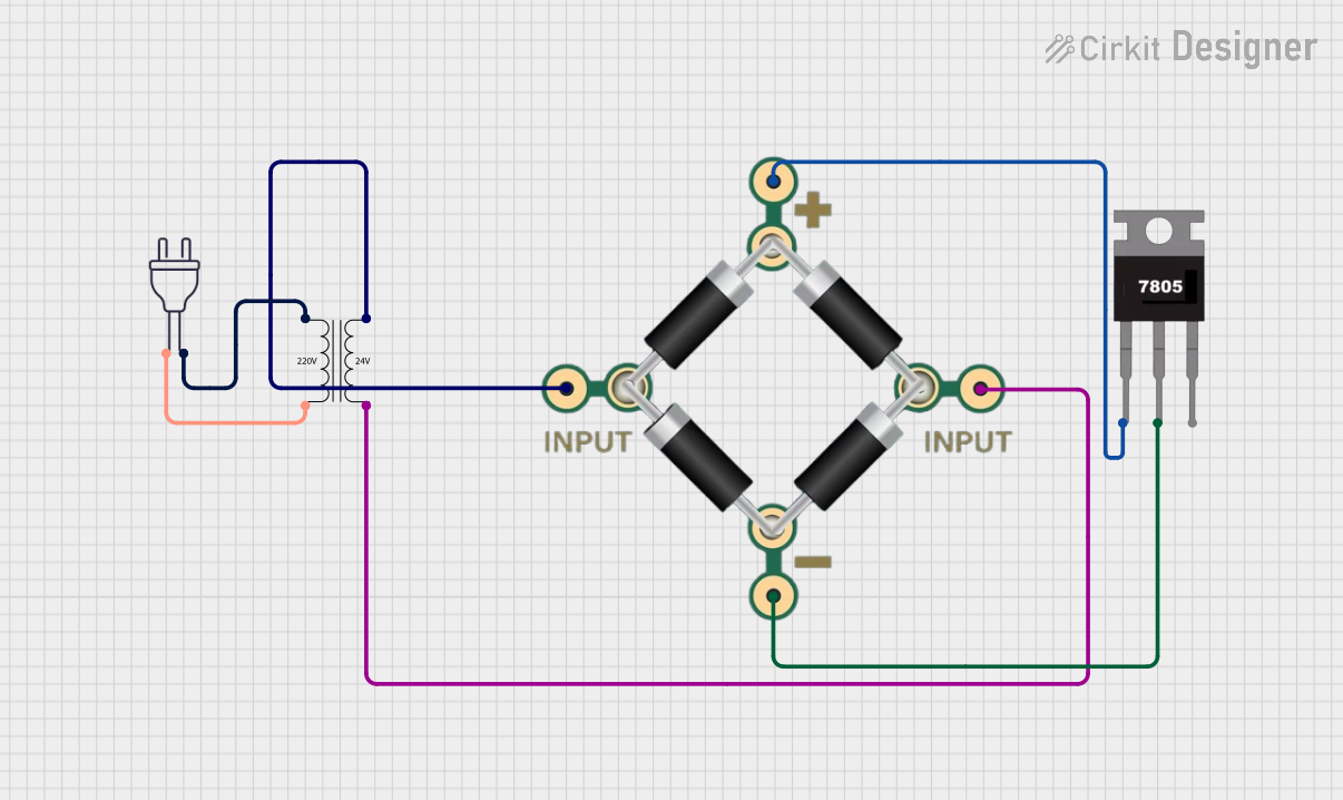
The pinout of a 12V to 5V regulator depends on its type. Below is an example for a common linear regulator (e.g., LM7805) and a DC-DC buck converter module.
Linear Regulator (e.g., LM7805)
| Pin | Name | Description |
|---|---|---|
| 1 | Input (Vin) | Connect to the 12V input voltage source. |
| 2 | Ground (GND) | Common ground for input and output. |
| 3 | Output (Vout) | Provides the regulated 5V output voltage. |
DC-DC Buck Converter Module
| Pin | Name | Description |
|---|---|---|
| IN+ | Input (+) | Connect to the positive terminal of the 12V source. |
| IN- | Input (-) | Connect to the negative terminal (ground). |
| OUT+ | Output (+) | Provides the regulated 5V output voltage. |
| OUT- | Output (-) | Common ground for the output. |
Usage Instructions
How to Use the Component in a Circuit
- Connect the Input Voltage:
- For a linear regulator, connect the 12V input to the
Vinpin and ground to theGNDpin. - For a DC-DC buck converter, connect the 12V source to the
IN+andIN-terminals.
- For a linear regulator, connect the 12V input to the
- Connect the Output Voltage:
- For a linear regulator, connect the
Voutpin to the load requiring 5V. - For a DC-DC buck converter, connect the load to the
OUT+andOUT-terminals.
- For a linear regulator, connect the
- Add Capacitors (if required):
- For linear regulators, place a 0.33µF capacitor on the input and a 0.1µF capacitor on the output to stabilize the voltage.
- For DC-DC converters, ensure the onboard capacitors are sufficient for your load.
- Verify Connections:
- Double-check all connections to avoid short circuits or incorrect wiring.
- Power On:
- Apply the 12V input voltage and measure the output to confirm a stable 5V.
Important Considerations and Best Practices
- Heat Dissipation: Linear regulators like the LM7805 can generate heat during operation. Use a heatsink if the current exceeds 500mA.
- Efficiency: For high-current applications, prefer a DC-DC buck converter over a linear regulator to minimize power loss.
- Input Voltage Range: Ensure the input voltage is within the specified range to avoid damage to the regulator.
- Load Current: Do not exceed the maximum output current rating of the regulator.
Example: Using a 12V to 5V Regulator with Arduino UNO
Below is an example of connecting a DC-DC buck converter to power an Arduino UNO:
Circuit Connections
- Connect the
IN+terminal of the buck converter to the 12V power source. - Connect the
IN-terminal to the ground of the power source. - Connect the
OUT+terminal to the Arduino's5Vpin. - Connect the
OUT-terminal to the Arduino'sGNDpin.
Arduino Code Example
// Example code to blink an LED using Arduino UNO powered by a 12V to 5V regulator

const int ledPin = 13; // Pin connected to the onboard LED

void setup() {
  pinMode(ledPin, OUTPUT); // Set the LED pin as an output
}

void loop() {
  digitalWrite(ledPin, HIGH); // Turn the LED on
  delay(1000);                // Wait for 1 second
  digitalWrite(ledPin, LOW);  // Turn the LED off
  delay(1000);                // Wait for 1 second
}
Troubleshooting and FAQs
Common Issues and Solutions
No Output Voltage:
- Cause: Incorrect wiring or loose connections.
- Solution: Verify all connections and ensure the input voltage is within the specified range.
Overheating:
- Cause: Excessive current draw or insufficient heat dissipation.
- Solution: Use a heatsink for linear regulators or switch to a DC-DC converter for higher efficiency.
Output Voltage Fluctuations:
- Cause: Insufficient input/output capacitors or unstable input voltage.
- Solution: Add appropriate capacitors as recommended in the datasheet.
Load Not Powering On:
- Cause: Load current exceeds the regulator's maximum rating.
- Solution: Use a regulator with a higher current rating or reduce the load.
FAQs
Q1: Can I use a 12V to 5V regulator with a 9V input?
A1: Yes, as long as the input voltage is within the regulator's specified range (e.g., 7V to 24V).
Q2: What is the difference between a linear regulator and a DC-DC converter?
A2: A linear regulator dissipates excess energy as heat, making it less efficient, while a DC-DC converter uses switching technology to achieve higher efficiency.
Q3: Can I power multiple devices with a single 12V to 5V regulator?
A3: Yes, but ensure the total current draw of all devices does not exceed the regulator's maximum output current.
Q4: Why is my regulator outputting less than 5V?
A4: This could be due to excessive load, insufficient input voltage, or a faulty regulator. Check the input voltage and load current.