Cirkit Designer Logo
Cirkit Designer
Your all-in-one circuit design IDE
Home / 
Component Documentation

How to Use ESP32 C5: Examples, Pinouts, and Specs

Image of ESP32 C5
Cirkit Designer LogoDesign with ESP32 C5 in Cirkit Designer

Introduction

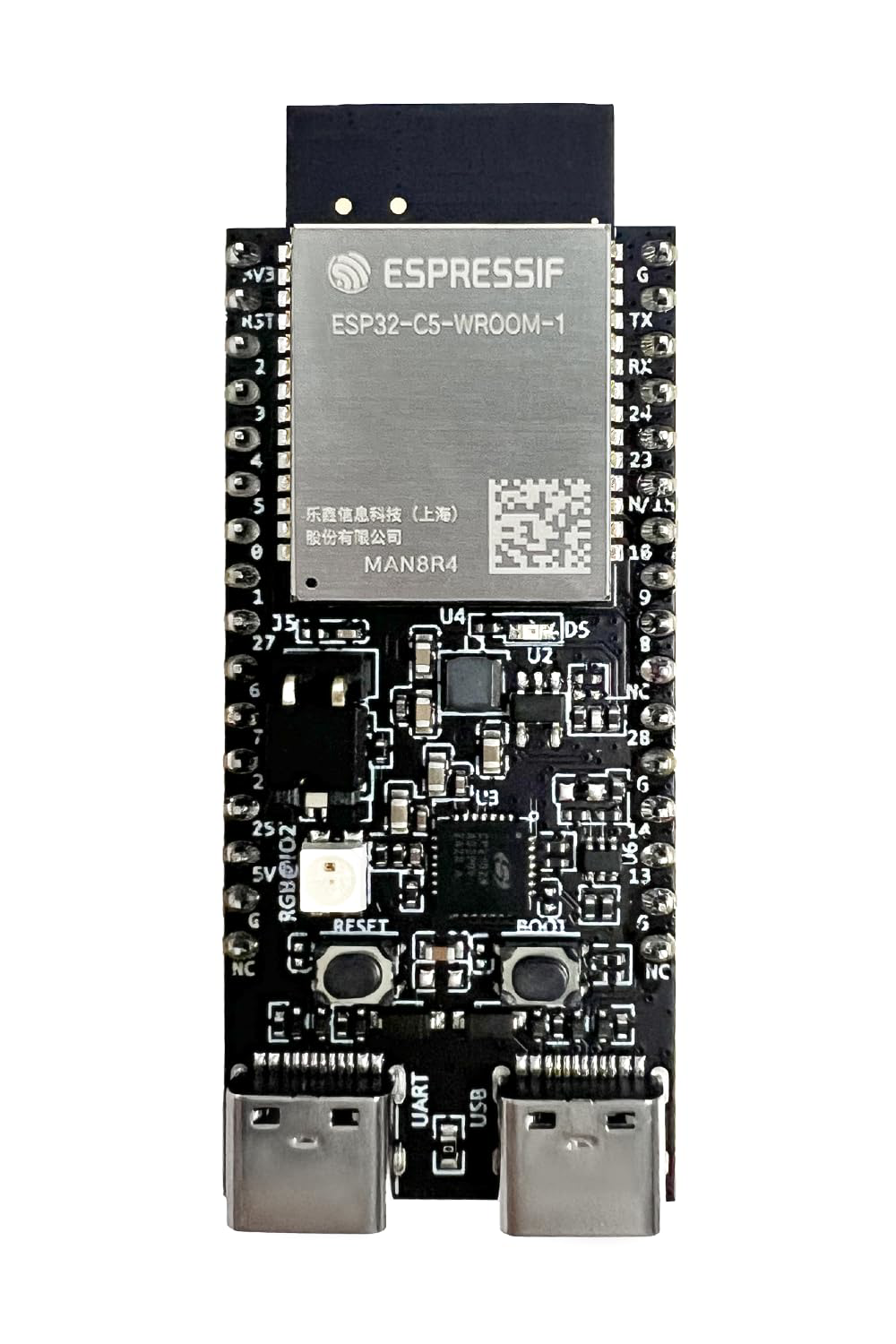
The ESP32 C5 is a powerful and versatile microcontroller designed for Internet of Things (IoT) applications. It features integrated Wi-Fi and Bluetooth capabilities, a dual-core processor, and a wide range of GPIO pins. The ESP32 C5 supports multiple communication protocols, making it an excellent choice for smart devices, home automation, industrial control systems, and wearable technology.

Explore Projects Built with ESP32 C5

Use Cirkit Designer to design, explore, and prototype these projects online. Some projects support real-time simulation. Click "Open Project" to start designing instantly!
ESP32C3 and LoRa-Enabled Environmental Sensing Node
Image of temperature_KA: A project utilizing ESP32 C5 in a practical application
This circuit features an ESP32C3 Supermini microcontroller connected to a LORA_RA02 module and a DHT11 temperature and humidity sensor. The ESP32C3 handles communication with the LORA module via SPI (using GPIO05, GPIO06, GPIO10, and GPIO04 for MISO, MOSI, NSS, and SCK respectively) and GPIO01 and GPIO02 for additional control signals. The DHT11 sensor is interfaced through GPIO03 for data reading, and all components share a common power supply through the 3.3V and GND pins.
Cirkit Designer LogoOpen Project in Cirkit Designer
ESP32-Based Smart Environment Monitoring System with GPS Tracking and OLED Display
Image of proj: A project utilizing ESP32 C5 in a practical application
This circuit features an ESP32 microcontroller configured to read temperature data from a DHT11 sensor, control a relay based on the temperature, and communicate with a GPS module for location tracking. It also interfaces with an ESP32 CAM module for video capture and an OLED display to show temperature readings. The ESP32's embedded code manages sensor data acquisition, relay control, display updates, and serial communication with the GPS module.
Cirkit Designer LogoOpen Project in Cirkit Designer
Battery-Powered ESP32 CAM with D500 Sensor for Wireless Monitoring
Image of PBL 2: A project utilizing ESP32 C5 in a practical application
This circuit features an ESP32 CAM module interfaced with a D500 sensor, powered by a Polymer Lithium Ion Battery through a Step Up Boost converter. The ESP32 CAM handles data processing and communication, while the D500 sensor provides input signals, with the boost converter ensuring a stable 5V supply from the battery.
Cirkit Designer LogoOpen Project in Cirkit Designer
ESP32-Based Sensor Monitoring System with OLED Display and E-Stop
Image of MVP_design: A project utilizing ESP32 C5 in a practical application
This circuit features an ESP32 microcontroller that interfaces with a variety of sensors and output devices. It is powered by a Lipo battery through a buck converter, ensuring a stable voltage supply. The ESP32 collects data from a DHT11 temperature and humidity sensor and a vibration sensor, controls a buzzer, and displays information on an OLED screen. An emergency stop (E Stop) is connected for safety purposes, allowing the system to be quickly deactivated.
Cirkit Designer LogoOpen Project in Cirkit Designer

Explore Projects Built with ESP32 C5

Use Cirkit Designer to design, explore, and prototype these projects online. Some projects support real-time simulation. Click "Open Project" to start designing instantly!
Image of temperature_KA: A project utilizing ESP32 C5 in a practical application
ESP32C3 and LoRa-Enabled Environmental Sensing Node
This circuit features an ESP32C3 Supermini microcontroller connected to a LORA_RA02 module and a DHT11 temperature and humidity sensor. The ESP32C3 handles communication with the LORA module via SPI (using GPIO05, GPIO06, GPIO10, and GPIO04 for MISO, MOSI, NSS, and SCK respectively) and GPIO01 and GPIO02 for additional control signals. The DHT11 sensor is interfaced through GPIO03 for data reading, and all components share a common power supply through the 3.3V and GND pins.
Cirkit Designer LogoOpen Project in Cirkit Designer
Image of proj: A project utilizing ESP32 C5 in a practical application
ESP32-Based Smart Environment Monitoring System with GPS Tracking and OLED Display
This circuit features an ESP32 microcontroller configured to read temperature data from a DHT11 sensor, control a relay based on the temperature, and communicate with a GPS module for location tracking. It also interfaces with an ESP32 CAM module for video capture and an OLED display to show temperature readings. The ESP32's embedded code manages sensor data acquisition, relay control, display updates, and serial communication with the GPS module.
Cirkit Designer LogoOpen Project in Cirkit Designer
Image of PBL 2: A project utilizing ESP32 C5 in a practical application
Battery-Powered ESP32 CAM with D500 Sensor for Wireless Monitoring
This circuit features an ESP32 CAM module interfaced with a D500 sensor, powered by a Polymer Lithium Ion Battery through a Step Up Boost converter. The ESP32 CAM handles data processing and communication, while the D500 sensor provides input signals, with the boost converter ensuring a stable 5V supply from the battery.
Cirkit Designer LogoOpen Project in Cirkit Designer
Image of MVP_design: A project utilizing ESP32 C5 in a practical application
ESP32-Based Sensor Monitoring System with OLED Display and E-Stop
This circuit features an ESP32 microcontroller that interfaces with a variety of sensors and output devices. It is powered by a Lipo battery through a buck converter, ensuring a stable voltage supply. The ESP32 collects data from a DHT11 temperature and humidity sensor and a vibration sensor, controls a buzzer, and displays information on an OLED screen. An emergency stop (E Stop) is connected for safety purposes, allowing the system to be quickly deactivated.
Cirkit Designer LogoOpen Project in Cirkit Designer

Common Applications

  • Smart home devices (e.g., smart lights, thermostats)
  • Industrial automation and monitoring
  • Wearable technology
  • Wireless sensor networks
  • Robotics and drones
  • IoT prototyping and development

Technical Specifications

The ESP32 C5 is packed with features that make it suitable for a variety of applications. Below are its key technical specifications:

General Specifications

Feature Description
Processor Dual-core Xtensa LX7 @ 240 MHz
Wireless Connectivity Wi-Fi 6 (802.11ax) and Bluetooth 5.0
Flash Memory Up to 16 MB
SRAM 512 KB
GPIO Pins 34
Operating Voltage 3.3V
Power Supply Range 2.7V to 3.6V
Communication Protocols UART, SPI, I2C, I2S, CAN, PWM
ADC Channels 18
DAC Channels 2
Operating Temperature -40°C to 85°C

Pin Configuration

The ESP32 C5 has a total of 34 GPIO pins, each with multiple functions. Below is a summary of the pin configuration:

Pin Number Default Function Alternate Functions
GPIO0 Input/Output Boot Mode Selection, PWM
GPIO1 UART TX General Purpose I/O, SPI
GPIO2 Input/Output ADC, PWM
GPIO3 UART RX General Purpose I/O, SPI
GPIO4 Input/Output ADC, PWM, I2C SDA
GPIO5 Input/Output ADC, PWM, I2C SCL
GPIO12 Input/Output ADC, PWM, Touch Sensor
GPIO13 Input/Output ADC, PWM, Touch Sensor
GPIO14 Input/Output ADC, PWM, Touch Sensor
GPIO15 Input/Output ADC, PWM, Touch Sensor
GPIO16 Input/Output UART, SPI
GPIO17 Input/Output UART, SPI

Note: Some GPIO pins have specific restrictions or are used during boot. Refer to the ESP32 C5 datasheet for detailed pin behavior.

Usage Instructions

The ESP32 C5 is easy to integrate into a variety of projects. Below are the steps and best practices for using the ESP32 C5 in a circuit.

Basic Circuit Setup

  1. Power Supply: Connect the ESP32 C5 to a 3.3V power source. Ensure the power supply can provide sufficient current (at least 500 mA).
  2. GPIO Connections: Use the GPIO pins for input/output as needed. Avoid using reserved pins during boot.
  3. Programming: Use a USB-to-serial adapter to upload code to the ESP32 C5. The microcontroller is compatible with the Arduino IDE, ESP-IDF, and other development environments.

Example: Blinking an LED with Arduino IDE

Below is an example of how to blink an LED connected to GPIO2 using the Arduino IDE:

// Include the Arduino core library for ESP32
#include <Arduino.h>

// Define the GPIO pin where the LED is connected
#define LED_PIN 2

void setup() {
  // Set the LED pin as an output
  pinMode(LED_PIN, OUTPUT);
}

void loop() {
  // Turn the LED on
  digitalWrite(LED_PIN, HIGH);
  delay(1000); // Wait for 1 second

  // Turn the LED off
  digitalWrite(LED_PIN, LOW);
  delay(1000); // Wait for 1 second
}

Best Practices

  • Use level shifters if interfacing with 5V logic devices.
  • Avoid using GPIO0, GPIO2, and GPIO15 for critical functions, as they are used during boot.
  • Use decoupling capacitors near the power pins to reduce noise.
  • Ensure proper grounding to avoid communication issues.

Troubleshooting and FAQs

Common Issues

  1. ESP32 C5 Not Booting

    • Cause: Incorrect GPIO pin states during boot.
    • Solution: Ensure GPIO0 is pulled high and GPIO2 is not floating.
  2. Wi-Fi Connection Fails

    • Cause: Incorrect Wi-Fi credentials or weak signal.
    • Solution: Double-check the SSID and password. Use an external antenna if needed.
  3. Code Upload Fails

    • Cause: Incorrect COM port or baud rate.
    • Solution: Verify the correct COM port is selected in the IDE. Use a baud rate of 115200.
  4. Overheating

    • Cause: Excessive current draw or poor ventilation.
    • Solution: Ensure the power supply is within the recommended range and provide adequate cooling.

FAQs

Q: Can the ESP32 C5 be powered with 5V?
A: No, the ESP32 C5 operates at 3.3V. Use a voltage regulator if your power source is 5V.

Q: How do I reset the ESP32 C5?
A: Press the EN (Enable) button on the board to reset the microcontroller.

Q: Is the ESP32 C5 compatible with the Arduino IDE?
A: Yes, the ESP32 C5 can be programmed using the Arduino IDE. Install the ESP32 board package to get started.

Q: Can I use the ESP32 C5 for battery-powered projects?
A: Yes, the ESP32 C5 is suitable for battery-powered applications. Use deep sleep mode to conserve power.

By following this documentation, you can effectively use the ESP32 C5 in your projects and troubleshoot common issues.