How to Use MakerEdu Creator: Examples, Pinouts, and Specs
Introduction
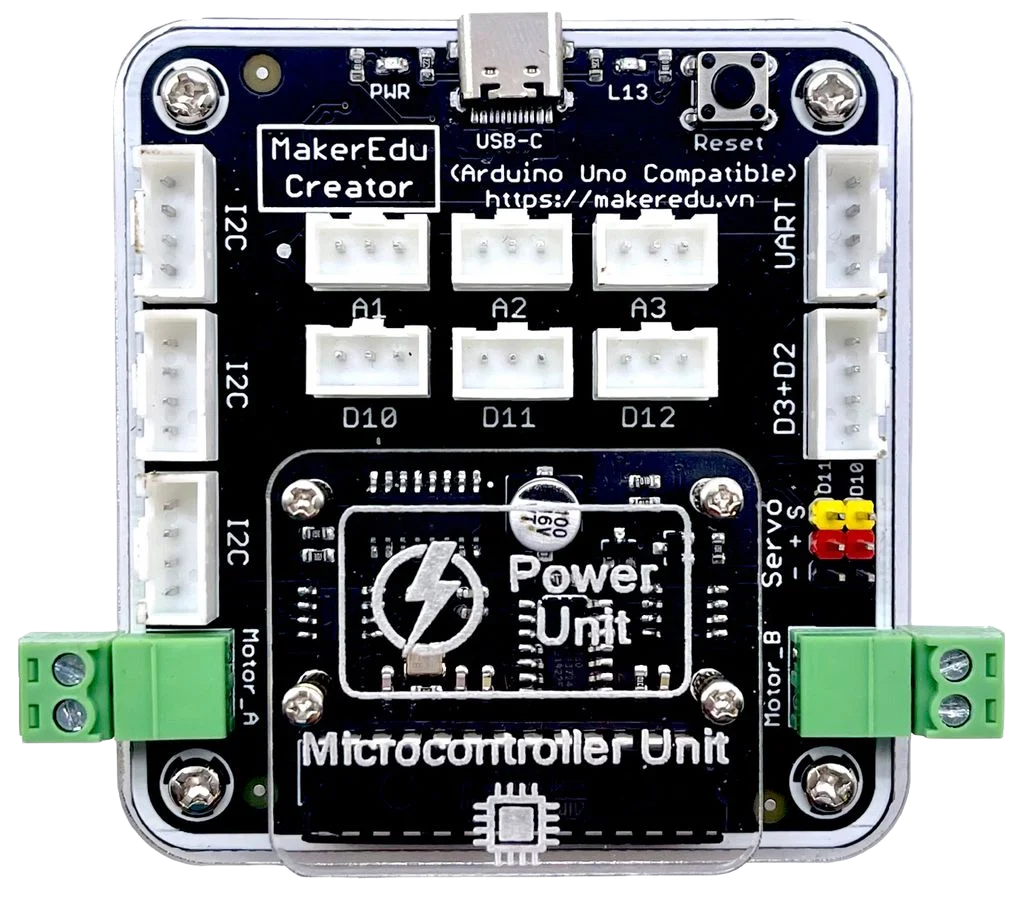
The MakerEdu Creator by Makerlabvn is a versatile educational platform designed for hands-on learning. It enables users to create, prototype, and experiment with electronics and coding projects. This component is ideal for students, educators, and hobbyists who want to explore the fundamentals of electronics and programming in an interactive and practical way.
Explore Projects Built with MakerEdu Creator

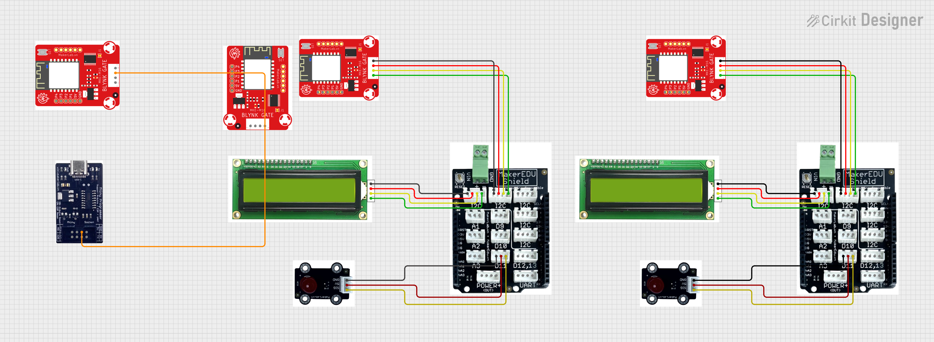
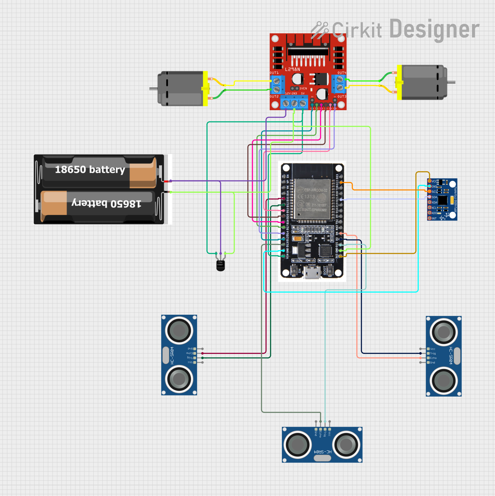
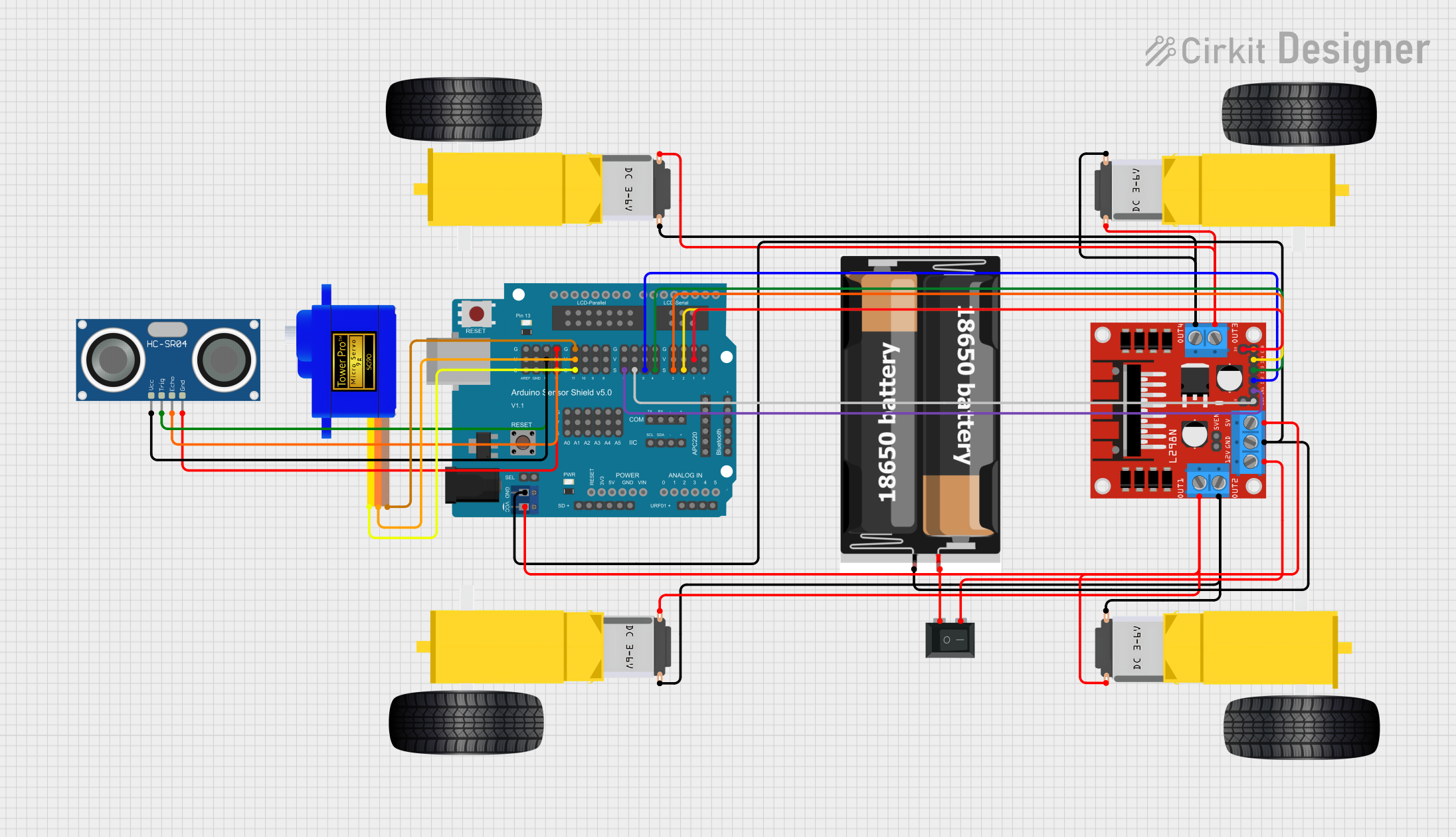
Explore Projects Built with MakerEdu Creator
Common Applications and Use Cases
- Educational projects for learning electronics and coding
- Rapid prototyping of small-scale electronic circuits
- Interactive STEM (Science, Technology, Engineering, and Mathematics) workshops
- DIY projects and maker activities
- Integration with microcontrollers like Arduino and Raspberry Pi
Technical Specifications
The MakerEdu Creator is designed to be user-friendly and compatible with a wide range of components and microcontrollers. Below are its key technical details:
Key Technical Details
| Parameter | Specification |
|---|---|
| Operating Voltage | 5V DC |
| Input Voltage Range | 4.5V - 5.5V DC |
| Maximum Current Output | 500mA |
| Communication Protocols | I2C, SPI, UART |
| GPIO Pins | 8 (Digital/Analog configurable) |
| Dimensions | 80mm x 60mm x 15mm |
| Weight | 50g |
| Compatibility | Arduino, Raspberry Pi, ESP32, etc. |
Pin Configuration and Descriptions
The MakerEdu Creator features a simple pin layout for easy integration with other components. Below is the pin configuration:
| Pin Number | Label | Description |
|---|---|---|
| 1 | VCC | Power input (5V DC) |
| 2 | GND | Ground connection |
| 3 | GPIO1 | General-purpose I/O pin (Digital/Analog) |
| 4 | GPIO2 | General-purpose I/O pin (Digital/Analog) |
| 5 | GPIO3 | General-purpose I/O pin (Digital/Analog) |
| 6 | GPIO4 | General-purpose I/O pin (Digital/Analog) |
| 7 | SDA | I2C Data Line |
| 8 | SCL | I2C Clock Line |
Usage Instructions
The MakerEdu Creator is designed to be beginner-friendly while offering advanced features for experienced users. Follow the steps below to use the component effectively:
How to Use the MakerEdu Creator in a Circuit
- Power the Board: Connect the VCC pin to a 5V DC power source and the GND pin to ground.
- Connect Peripherals: Use the GPIO pins to connect sensors, actuators, or other components. Configure the pins as digital or analog as needed.
- Communication: Use the I2C (SDA, SCL) or UART pins to interface with microcontrollers like Arduino or Raspberry Pi.
- Programming: Write and upload code to your microcontroller to control the MakerEdu Creator and connected peripherals.
Important Considerations and Best Practices
- Ensure the input voltage does not exceed 5.5V to avoid damaging the board.
- Use pull-up resistors for I2C communication if not already included in your setup.
- Avoid drawing more than 500mA of current to prevent overheating.
- Double-check all connections before powering the board to prevent short circuits.
Example: Using MakerEdu Creator with Arduino UNO
Below is an example of how to use the MakerEdu Creator with an Arduino UNO to read an analog sensor and control an LED:
// Example: Reading an analog sensor and controlling an LED with MakerEdu Creator

const int sensorPin = A0; // Connect the sensor to GPIO1 (Analog pin A0)
const int ledPin = 9;     // Connect the LED to GPIO2 (Digital pin 9)

void setup() {
  pinMode(ledPin, OUTPUT); // Set GPIO2 as an output pin
  Serial.begin(9600);      // Initialize serial communication
}

void loop() {
  int sensorValue = analogRead(sensorPin); // Read the analog value from the sensor
  Serial.println(sensorValue);            // Print the sensor value to the Serial Monitor

  // Map the sensor value to a PWM range (0-255) and write to the LED
  int ledBrightness = map(sensorValue, 0, 1023, 0, 255);
  analogWrite(ledPin, ledBrightness);

  delay(100); // Small delay for stability
}
Troubleshooting and FAQs
Common Issues and Solutions
The board is not powering on.
- Ensure the VCC pin is connected to a stable 5V DC power source.
- Check for loose or incorrect connections.
I2C communication is not working.
- Verify that the SDA and SCL lines are correctly connected to the microcontroller.
- Use pull-up resistors (typically 4.7kΩ) on the SDA and SCL lines if required.
GPIO pins are not responding.
- Confirm that the pins are configured correctly in your code (e.g., as INPUT or OUTPUT).
- Check for short circuits or incorrect wiring.
The board overheats during operation.
- Ensure the current draw does not exceed 500mA.
- Check for any components that might be causing a short circuit.
FAQs
Q: Can the MakerEdu Creator be powered by a battery?
A: Yes, as long as the battery provides a stable voltage within the range of 4.5V to 5.5V.
Q: Is the MakerEdu Creator compatible with 3.3V logic devices?
A: Yes, but you may need level shifters to safely interface 3.3V devices with the 5V GPIO pins.
Q: Can I use the MakerEdu Creator with a Raspberry Pi?
A: Absolutely! The MakerEdu Creator is compatible with Raspberry Pi and can be connected via GPIO or I2C.
Q: Does the board include built-in pull-up resistors for I2C?
A: No, you will need to add external pull-up resistors if your setup requires them.
By following this documentation, you can effectively use the MakerEdu Creator for a wide range of educational and prototyping projects.