How to Use splicing connector 4: Examples, Pinouts, and Specs
Introduction
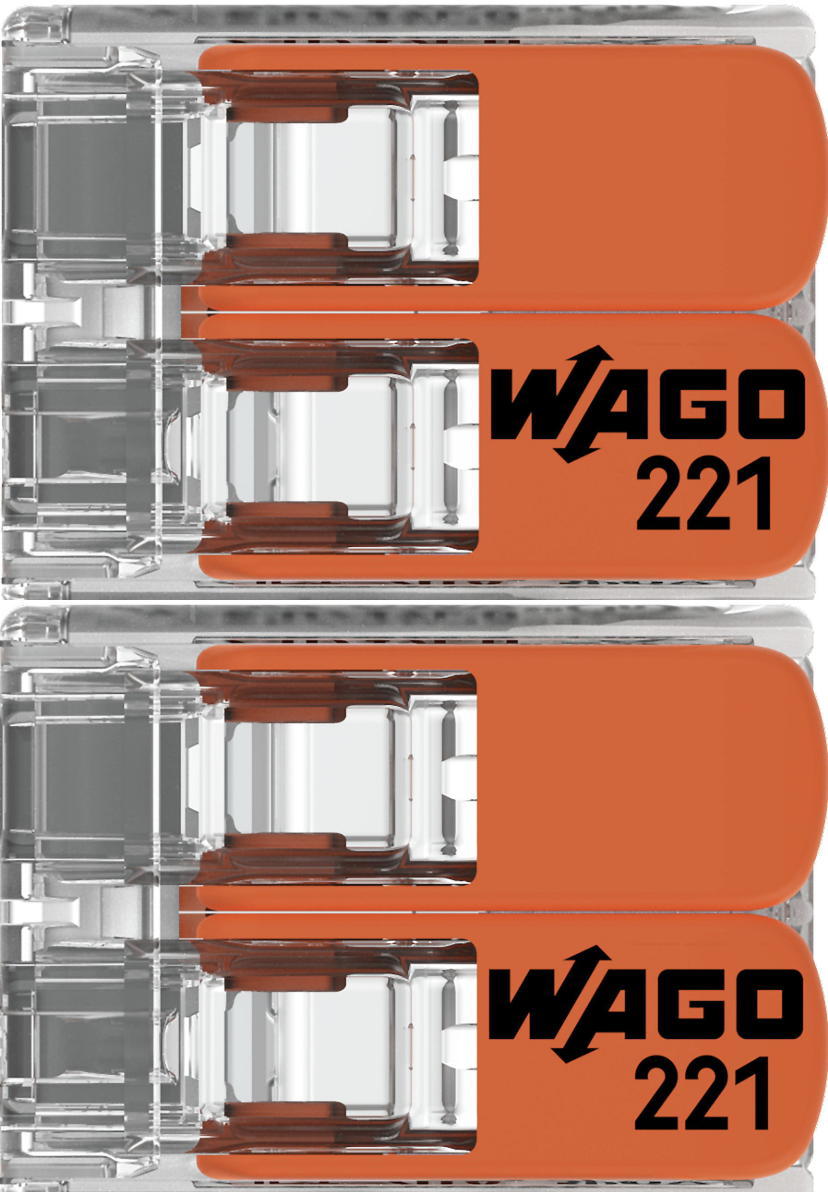
The Splicing Connector 4 by WAGO is a compact and reliable electrical connector designed to join two or more wires securely. It ensures a stable and durable electrical connection while maintaining the integrity of the circuit. This connector is particularly useful in applications where quick and tool-free wire connections are required.
Explore Projects Built with splicing connector 4


Explore Projects Built with splicing connector 4
Common Applications and Use Cases
- Electrical wiring in residential, commercial, and industrial installations
- Connecting wires in lighting systems, control panels, and junction boxes
- Temporary or permanent wire splicing in prototyping and testing setups
- Ideal for use in confined spaces due to its compact design
Technical Specifications
The following table outlines the key technical details of the Splicing Connector 4:
| Parameter | Specification |
|---|---|
| Manufacturer | WAGO |
| Part ID | Splicing Connector |
| Number of Connections | 4 |
| Wire Size Compatibility | 28–12 AWG (solid or stranded wires) |
| Voltage Rating | 450 V AC |
| Current Rating | 32 A |
| Operating Temperature | -35°C to +85°C |
| Housing Material | Polycarbonate (flame-retardant, UL94-V0) |
| Connection Type | Push-in spring technology |
| Dimensions (L x W x H) | 20.5 mm x 18.6 mm x 8.3 mm |
Pin Configuration and Descriptions
The Splicing Connector 4 does not have traditional pins but features four wire entry points. Each entry point corresponds to a single wire connection. The table below describes the wire entry points:
| Entry Point | Description |
|---|---|
| 1 | Wire connection 1 (input/output) |
| 2 | Wire connection 2 (input/output) |
| 3 | Wire connection 3 (input/output) |
| 4 | Wire connection 4 (input/output) |
Usage Instructions
How to Use the Splicing Connector 4 in a Circuit
- Prepare the Wires: Strip the insulation from the wire ends, leaving approximately 10–12 mm of exposed conductor.
- Insert the Wires: Push the stripped wire ends into the connector's entry points. Ensure the wire is fully seated and makes contact with the internal spring mechanism.
- Verify the Connection: Gently tug on the wires to confirm they are securely held in place.
- Connect to the Circuit: Once all wires are connected, integrate the splicing connector into your circuit as needed.
Important Considerations and Best Practices
- Ensure the wire size is within the specified range (28–12 AWG) for optimal performance.
- Avoid over-stripping the wire insulation, as this may lead to exposed conductors outside the connector.
- Do not exceed the voltage and current ratings of the connector to prevent overheating or failure.
- Use the connector in environments within the specified operating temperature range (-35°C to +85°C).
- For stranded wires, twist the strands together before inserting them into the connector to ensure a secure connection.
Example: Connecting to an Arduino UNO
While the Splicing Connector 4 is not directly connected to an Arduino UNO, it can be used to simplify wiring in Arduino-based projects. For example, you can use the connector to join multiple ground wires or power supply lines.
// Example: Using Splicing Connector 4 to distribute power in an Arduino project

// Connect the 5V pin of the Arduino UNO to one entry point of the splicing connector.
// Use the remaining entry points to distribute 5V power to multiple components, such as
// sensors or modules.

void setup() {
  // Initialize components connected to the splicing connector
  pinMode(13, OUTPUT); // Example: LED connected to pin 13
}

void loop() {
  digitalWrite(13, HIGH); // Turn on the LED
  delay(1000);            // Wait for 1 second
  digitalWrite(13, LOW);  // Turn off the LED
  delay(1000);            // Wait for 1 second
}
Troubleshooting and FAQs
Common Issues and Solutions
Loose Wire Connections
- Issue: Wires are not securely held in the connector.
- Solution: Ensure the wire is fully inserted into the entry point and makes contact with the spring mechanism. Check that the wire size is within the specified range (28–12 AWG).
Overheating
- Issue: The connector becomes warm or hot during operation.
- Solution: Verify that the current passing through the connector does not exceed the 32 A rating. Check for loose connections that may cause resistance and heat buildup.
Wire Slippage
- Issue: Stranded wires slip out of the connector.
- Solution: Twist the strands together before inserting them into the connector to ensure a secure grip.
FAQs
Can the Splicing Connector 4 be reused?
- Yes, the connector can be reused. Simply remove the wires by pulling them out and insert new wires as needed.
Is the connector suitable for outdoor use?
- The connector is not waterproof. If used outdoors, ensure it is placed in a weatherproof enclosure.
Can I connect wires of different sizes?
- Yes, the connector supports a range of wire sizes (28–12 AWG). However, ensure each wire is securely seated.
What tools are required for installation?
- No tools are required. The push-in spring technology allows for tool-free installation.
By following this documentation, you can effectively use the WAGO Splicing Connector 4 in your electrical and electronic projects.