How to Use RAK19007 WisBlock Base Board 2nd Gen: Examples, Pinouts, and Specs
Introduction
The RAK19007 WisBlock Base Board 2nd Gen is a versatile and robust base board designed by RAK Wireless for the WisBlock ecosystem. It serves as the foundation for integrating various WisBlock modules, including sensors, communication modules, and power management units. This base board simplifies the prototyping and development of IoT applications by providing seamless connectivity and efficient power management.
Explore Projects Built with RAK19007 WisBlock Base Board 2nd Gen


Explore Projects Built with RAK19007 WisBlock Base Board 2nd Gen
Common Applications and Use Cases
- IoT prototyping and development
- Smart agriculture and environmental monitoring
- Industrial automation and control systems
- Smart cities and home automation
- Wearable and portable IoT devices
Technical Specifications
Key Technical Details
| Parameter | Specification |
|---|---|
| Manufacturer | RAK Wireless |
| Part Number | RAK19007 |
| Dimensions | 54 mm x 25 mm x 6 mm |
| Operating Voltage | 3.3V - 5V |
| Power Supply Options | USB-C, Li-Ion/Li-Po battery, or external power source |
| Battery Charging Support | Integrated Li-Ion/Li-Po battery charging circuit |
| Connector Type | WisBlock-compatible slots for Core, IO, Sensor, and Communication modules |
| Communication Interfaces | I2C, UART, SPI, GPIO |
| Mounting Options | Screw holes for secure mounting |
| Operating Temperature Range | -40°C to +85°C |
Pin Configuration and Descriptions
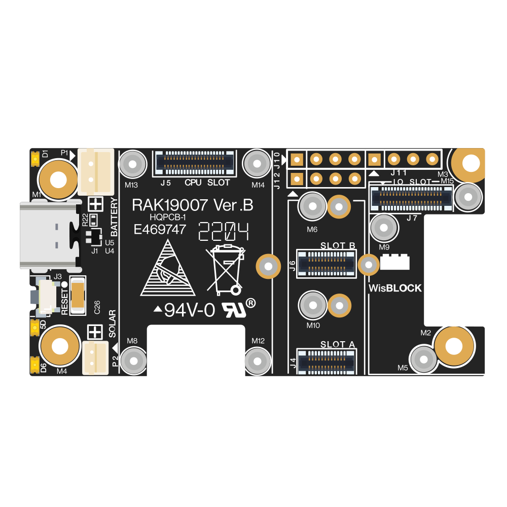
The RAK19007 features multiple connectors for WisBlock modules. Below is a description of the key connectors:
WisBlock Slot Descriptions
| Slot Name | Purpose | Description |
|---|---|---|
| Core Slot | Main processing unit | Connects to WisBlock Core modules (e.g., RAK4631) for processing and control. |
| IO Slot | Input/Output expansion | Allows connection of IO modules for additional GPIO or communication interfaces. |
| Sensor Slot | Sensor integration | Connects to WisBlock Sensor modules for data acquisition. |
| Comm Slot | Communication module integration | Supports WisBlock Communication modules (e.g., LoRa, BLE, Wi-Fi). |
Power and USB-C Connector
| Pin/Connector | Description |
|---|---|
| USB-C | Provides power to the board and connected modules. Also used for programming. |
| Battery JST | JST connector for Li-Ion/Li-Po battery connection. |
| 5V Pin | External 5V power input for powering the board. |
Usage Instructions
How to Use the RAK19007 in a Circuit
- Connect the WisBlock Core Module: Insert the WisBlock Core module (e.g., RAK4631) into the Core Slot.
- Add Sensor and Communication Modules: Attach compatible WisBlock Sensor and Communication modules to their respective slots.
- Power the Board:
- Use a USB-C cable to power the board and program the Core module.
- Alternatively, connect a Li-Ion/Li-Po battery to the Battery JST connector.
- For external power, supply 5V to the 5V Pin.
- Program the Core Module: Use the USB-C connection to upload firmware to the Core module via a development environment like Arduino IDE or PlatformIO.
- Monitor and Debug: Use the USB-C connection for serial communication to monitor and debug your application.
Important Considerations and Best Practices
- Ensure the correct orientation of modules when inserting them into the slots to avoid damage.
- Use only compatible WisBlock modules to ensure proper functionality.
- If using a battery, ensure it is a Li-Ion or Li-Po battery with the correct voltage and capacity.
- Avoid exceeding the operating temperature range (-40°C to +85°C) to prevent damage to the board and modules.
- Secure the board using the mounting holes to prevent accidental disconnections during operation.
Example: Using RAK19007 with Arduino UNO-Compatible Code
Below is an example of how to use the RAK19007 with a WisBlock Core module (e.g., RAK4631) to read data from a connected sensor module:
#include <Wire.h>

// Define I2C address of the sensor module
#define SENSOR_I2C_ADDRESS 0x76

void setup() {
  Serial.begin(115200); // Initialize serial communication for debugging
  Wire.begin();         // Initialize I2C communication

  // Check if the sensor module is connected
  Wire.beginTransmission(SENSOR_I2C_ADDRESS);
  if (Wire.endTransmission() == 0) {
    Serial.println("Sensor module detected!");
  } else {
    Serial.println("Sensor module not detected. Check connections.");
  }
}

void loop() {
  // Example: Read data from the sensor module
  Wire.beginTransmission(SENSOR_I2C_ADDRESS);
  Wire.write(0x00); // Send a command to the sensor (e.g., read data register)
  Wire.endTransmission();

  Wire.requestFrom(SENSOR_I2C_ADDRESS, 2); // Request 2 bytes of data
  if (Wire.available() == 2) {
    int data = Wire.read() << 8 | Wire.read(); // Combine two bytes into one value
    Serial.print("Sensor Data: ");
    Serial.println(data);
  } else {
    Serial.println("Failed to read data from sensor.");
  }

  delay(1000); // Wait 1 second before the next reading
}
Troubleshooting and FAQs
Common Issues and Solutions
Modules Not Detected:
- Ensure all modules are properly seated in their respective slots.
- Check for bent or damaged pins on the connectors.
- Verify that the Core module is powered and running correctly.
No Power to the Board:
- Confirm that the USB-C cable or battery is properly connected.
- Check the power source for sufficient voltage and current.
Communication Errors:
- Ensure the correct I2C, UART, or SPI addresses are used in the code.
- Verify that the modules are compatible with the Core module.
Overheating:
- Avoid operating the board outside the specified temperature range.
- Ensure proper ventilation and avoid short circuits.
FAQs
Q: Can I use the RAK19007 without a battery?
A: Yes, the board can be powered via USB-C or an external 5V power source without a battery.
Q: What WisBlock Core modules are compatible with the RAK19007?
A: The RAK19007 is compatible with WisBlock Core modules such as the RAK4631.
Q: How do I update the firmware on the Core module?
A: Use the USB-C connection to upload firmware via Arduino IDE, PlatformIO, or other supported tools.
Q: Can I use multiple sensor modules simultaneously?
A: Yes, as long as the modules do not conflict in terms of I2C addresses or other communication interfaces.
Q: Is the RAK19007 suitable for outdoor use?
A: The board itself is not weatherproof. Use an appropriate enclosure for outdoor applications.