How to Use FS800E: Examples, Pinouts, and Specs
Introduction
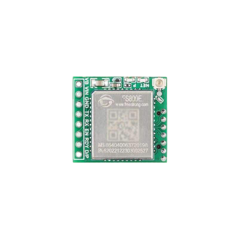
The FS800E, manufactured by Saya, is a high-performance, low-power MOSFET driver designed to drive power MOSFETs in a wide range of applications. It is optimized for fast switching speeds and low propagation delay, making it ideal for high-efficiency power supplies, motor control systems, and other applications requiring precise MOSFET control. The FS800E can drive both high-side and low-side MOSFETs efficiently, ensuring reliable operation in demanding environments.
Explore Projects Built with FS800E


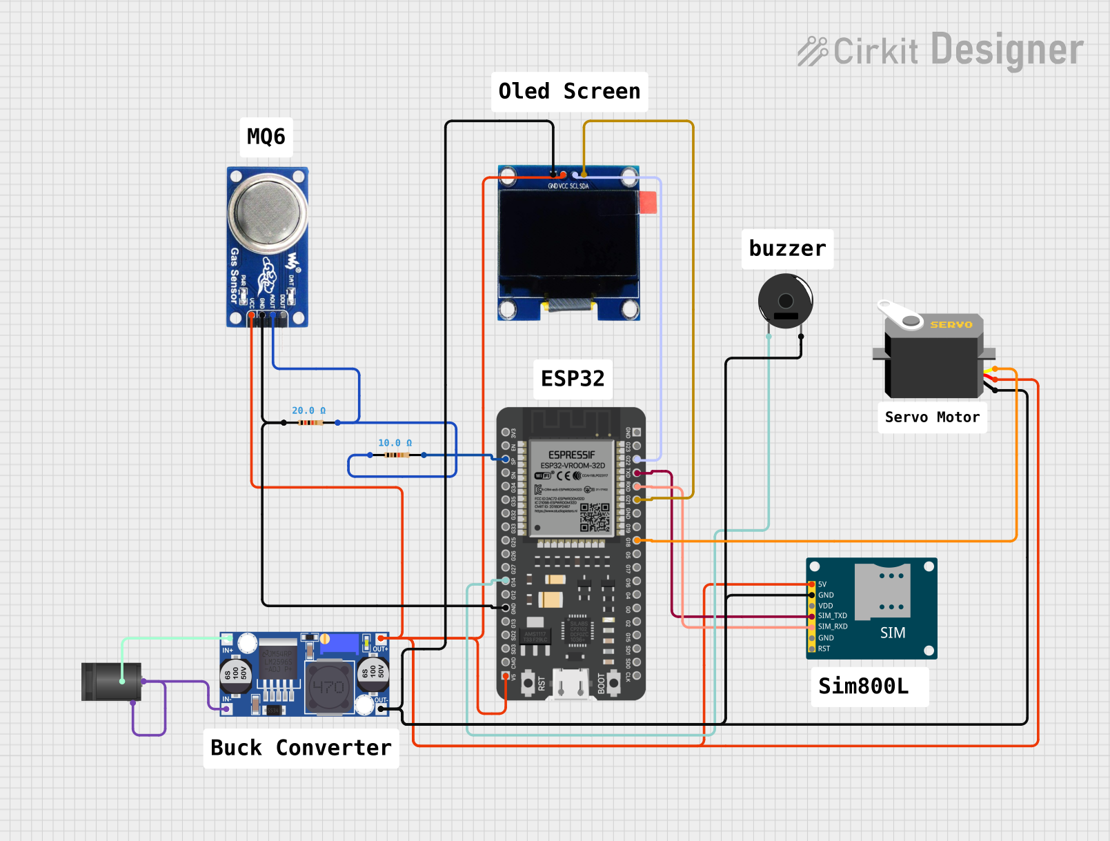
Explore Projects Built with FS800E
Common Applications
- Switched-mode power supplies (SMPS)
- Motor control systems
- DC-DC converters
- Inverters for renewable energy systems
- High-speed switching circuits
Technical Specifications
Key Specifications
| Parameter | Value |
|---|---|
| Supply Voltage (VDD) | 4.5V to 18V |
| Output Drive Current | 2A (peak) |
| Propagation Delay | 20ns (typical) |
| Operating Temperature | -40°C to +125°C |
| Input Logic Levels | TTL/CMOS compatible |
| Output Rise/Fall Time | 10ns (typical) |
| Package Type | 8-pin SOIC or DIP |
Pin Configuration and Descriptions
| Pin Number | Pin Name | Description |
|---|---|---|
| 1 | IN | Input signal for controlling the MOSFET driver. TTL/CMOS compatible. |
| 2 | GND | Ground connection. |
| 3 | VDD | Supply voltage input (4.5V to 18V). |
| 4 | OUT | Output signal to drive the MOSFET gate. |
| 5 | NC | No connection. Leave unconnected or grounded. |
| 6 | EN | Enable pin. High to enable the driver, low to disable. |
| 7 | HS | High-side MOSFET drive signal. |
| 8 | LS | Low-side MOSFET drive signal. |
Usage Instructions
Using the FS800E in a Circuit
- Power Supply: Connect the VDD pin to a stable power supply within the range of 4.5V to 18V. Ensure proper decoupling with a capacitor (e.g., 0.1µF ceramic capacitor) close to the VDD pin.
- Input Signal: Provide a TTL/CMOS-compatible signal to the IN pin to control the MOSFET driver. The input signal determines the state of the MOSFET being driven.
- Output Connection: Connect the OUT pin to the gate of the MOSFET. Use a gate resistor (e.g., 10Ω) to limit inrush current and reduce ringing.
- Enable Pin: Use the EN pin to enable or disable the driver. Pull the EN pin high to enable the driver or low to disable it.
- High-Side and Low-Side Driving: Use the HS and LS pins to drive high-side and low-side MOSFETs, respectively, in half-bridge or full-bridge configurations.
Important Considerations
- Decoupling: Always use a decoupling capacitor close to the VDD pin to ensure stable operation.
- Thermal Management: Ensure adequate cooling for the FS800E, especially in high-power applications.
- Signal Integrity: Minimize the length of PCB traces for the IN and OUT pins to reduce noise and signal degradation.
- Gate Resistor: Use an appropriate gate resistor to optimize switching speed and reduce EMI.
Example: Using FS800E with Arduino UNO
The FS800E can be controlled using an Arduino UNO to drive a MOSFET for switching a load. Below is an example circuit and code:
Circuit Connections
- Connect the VDD pin of the FS800E to the 5V pin of the Arduino.
- Connect the GND pin of the FS800E to the GND pin of the Arduino.
- Connect the IN pin of the FS800E to a digital output pin of the Arduino (e.g., pin 9).
- Connect the OUT pin of the FS800E to the gate of the MOSFET.
- Connect the source of the MOSFET to ground and the drain to the load.
Arduino Code
// Define the pin connected to the FS800E IN pin
const int driverPin = 9;

void setup() {
  // Set the driver pin as an output
  pinMode(driverPin, OUTPUT);
}

void loop() {
  // Turn the MOSFET on
  digitalWrite(driverPin, HIGH);
  delay(1000); // Keep the MOSFET on for 1 second

  // Turn the MOSFET off
  digitalWrite(driverPin, LOW);
  delay(1000); // Keep the MOSFET off for 1 second
}
Troubleshooting and FAQs
Common Issues and Solutions
No Output Signal on OUT Pin
- Cause: The EN pin is not pulled high.
- Solution: Ensure the EN pin is connected to a high logic level to enable the driver.
MOSFET Overheating
- Cause: Incorrect gate resistor value or excessive switching frequency.
- Solution: Use an appropriate gate resistor (e.g., 10Ω) and verify the switching frequency is within the MOSFET's specifications.
Driver Not Responding to Input Signal
- Cause: Input signal is not TTL/CMOS compatible or is outside the voltage range.
- Solution: Verify the input signal levels and ensure they are within the specified range.
High Noise on Output Signal
- Cause: Long PCB traces or insufficient decoupling.
- Solution: Minimize trace lengths and add a decoupling capacitor close to the VDD pin.
FAQs
Q1: Can the FS800E drive both N-channel and P-channel MOSFETs?
A1: The FS800E is primarily designed for driving N-channel MOSFETs. For P-channel MOSFETs, additional circuitry may be required.
Q2: What is the maximum switching frequency of the FS800E?
A2: The FS800E can operate at switching frequencies up to 1MHz, depending on the load and circuit design.
Q3: Is the FS800E suitable for driving IGBTs?
A3: While the FS800E is optimized for MOSFETs, it can drive IGBTs with similar gate drive requirements. However, verify the IGBT's gate charge and switching characteristics.
Q4: Can I use the FS800E in a 24V system?
A4: The FS800E's maximum supply voltage is 18V. For 24V systems, use a voltage regulator to step down the supply voltage to within the FS800E's operating range.
This concludes the documentation for the FS800E MOSFET driver. For further assistance, refer to the manufacturer's datasheet or contact Saya's technical support.