How to Use EZO EC Circuit: Examples, Pinouts, and Specs
Introduction
The EZO EC Circuit by Atlas Scientific is a compact and highly accurate electronic module designed for measuring the electrical conductivity (EC) of liquids. This module is capable of providing precise conductivity readings, making it an essential tool for applications that require monitoring and control of liquid quality. Its versatility and ease of integration make it suitable for a wide range of industries, including:
- Aquaculture: Monitoring water quality to ensure optimal conditions for aquatic life.
- Hydroponics: Measuring nutrient levels in water to maintain proper plant growth.
- Water Quality Testing: Assessing the purity and salinity of water in environmental and industrial settings.
The EZO EC Circuit is designed to work seamlessly with microcontrollers, such as the Arduino UNO, and can be easily integrated into custom systems.
Explore Projects Built with EZO EC Circuit

Explore Projects Built with EZO EC Circuit
Technical Specifications
Key Technical Details
- Input Voltage: 3.3V to 5V DC
- Current Consumption: ~4mA
- Communication Protocols: UART (default) and I2C
- Measurement Range: 0.07 µS/cm to 500,000 µS/cm
- Accuracy: ±2% of reading
- Temperature Compensation: Supported (requires an external temperature probe)
- Dimensions: 13.97mm x 20.32mm (0.55" x 0.8")
- Weight: ~1.4g
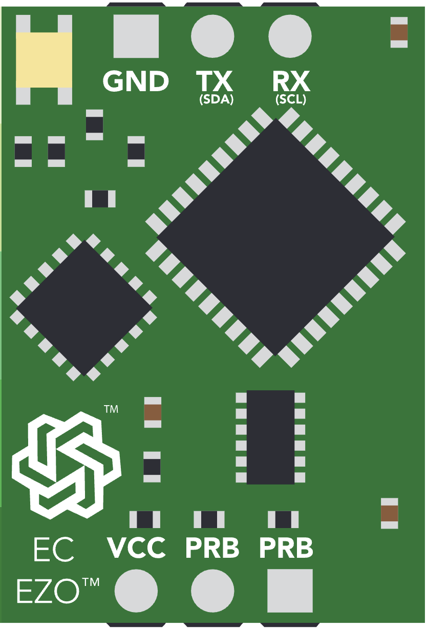
Pin Configuration and Descriptions
The EZO EC Circuit has a total of 6 pins. The table below describes each pin and its function:
| Pin | Name | Description |
|---|---|---|
| 1 | VCC | Power input (3.3V to 5V DC). |
| 2 | GND | Ground connection. |
| 3 | TX | UART Transmit pin. Sends data to the microcontroller. |
| 4 | RX | UART Receive pin. Receives data from the microcontroller. |
| 5 | PGND | Probe ground. Connects to the ground of the conductivity probe. |
| 6 | PWR_EN (I2C) | Power enable pin. Used to switch the circuit on/off or configure I2C mode. |
Usage Instructions
How to Use the EZO EC Circuit in a Circuit
- Powering the Circuit: Connect the
VCCpin to a 3.3V or 5V power source and theGNDpin to ground. - Connecting the Probe: Attach the conductivity probe to the circuit, ensuring the probe ground (
PGND) is properly connected. - Communication Setup:
- For UART mode (default), connect the
TXandRXpins to the corresponding UART pins on your microcontroller. - For I2C mode, pull the
PWR_ENpin low during startup to enable I2C communication.
- For UART mode (default), connect the
- Temperature Compensation: If temperature compensation is required, connect an external temperature probe to the circuit.
- Data Reading: Use the appropriate commands (via UART or I2C) to retrieve conductivity readings.
Important Considerations and Best Practices
- Calibration: Regularly calibrate the circuit using standard conductivity solutions to ensure accurate readings.
- Temperature Compensation: For precise measurements, always use temperature compensation, especially in environments with fluctuating temperatures.
- Probe Maintenance: Clean the conductivity probe regularly to prevent fouling, which can affect accuracy.
- Power Supply: Use a stable power source to avoid noise or fluctuations in readings.
- I2C Address: If using I2C mode, ensure the correct I2C address is configured to avoid conflicts with other devices.
Example Code for Arduino UNO (UART Mode)
#include <SoftwareSerial.h>

// Define the RX and TX pins for the EZO EC Circuit
#define RX_PIN 10  // Connect to the TX pin of the EZO EC Circuit
#define TX_PIN 11  // Connect to the RX pin of the EZO EC Circuit

// Create a SoftwareSerial object for communication
SoftwareSerial ezoEC(RX_PIN, TX_PIN);

void setup() {
  // Start the serial communication with the EZO EC Circuit
  ezoEC.begin(9600);  // Default baud rate for the EZO EC Circuit
  Serial.begin(9600); // Start the serial monitor for debugging

  Serial.println("EZO EC Circuit Example - UART Mode");
}

void loop() {
  // Send a command to the EZO EC Circuit to take a reading
  ezoEC.print("R\r"); // "R" command requests a reading, "\r" is the carriage return

  // Wait for the circuit to respond
  delay(1000);

  // Check if data is available from the EZO EC Circuit
  if (ezoEC.available()) {
    // Read and print the response from the circuit
    while (ezoEC.available()) {
      char c = ezoEC.read();
      Serial.print(c); // Print the response to the serial monitor
    }
    Serial.println(); // Add a newline for readability
  }

  delay(2000); // Wait before taking the next reading
}
Troubleshooting and FAQs
Common Issues and Solutions
No Response from the Circuit:
- Cause: Incorrect wiring or communication settings.
- Solution: Double-check the connections, ensure the correct baud rate (9600 for UART), and verify the power supply.
Inaccurate Readings:
- Cause: Probe fouling or lack of calibration.
- Solution: Clean the probe and recalibrate the circuit using standard conductivity solutions.
Temperature Compensation Not Working:
- Cause: Temperature probe not connected or configured.
- Solution: Ensure the temperature probe is properly connected and the circuit is configured for temperature compensation.
I2C Communication Issues:
- Cause: Incorrect I2C address or mode not enabled.
- Solution: Pull the
PWR_ENpin low during startup to enable I2C mode and verify the I2C address.
FAQs
Can the EZO EC Circuit be used with any conductivity probe?
- The circuit is designed to work with Atlas Scientific conductivity probes. Using other probes may result in inaccurate readings.
What is the lifespan of the conductivity probe?
- The lifespan depends on usage and maintenance. Regular cleaning and proper storage can extend the probe's life.
Can I use the circuit in a high-salinity environment?
- Yes, the EZO EC Circuit supports a wide measurement range, including high-salinity conditions.
How do I switch between UART and I2C modes?
- To enable I2C mode, pull the
PWR_ENpin low during startup. For UART mode, leave thePWR_ENpin unconnected or high.
- To enable I2C mode, pull the
This documentation provides a comprehensive guide to using the Atlas Scientific EZO EC Circuit effectively. For further details, refer to the official datasheet or contact Atlas Scientific support.