How to Use Arduino Mega Pro Mini: Examples, Pinouts, and Specs
Introduction
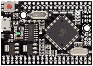
The Arduino Mega Pro Mini is a compact microcontroller board based on the ATmega2560 microcontroller. It is designed for projects that require a large number of input/output (I/O) pins while maintaining a small form factor. This board is ideal for advanced applications such as robotics, automation, and data acquisition systems. Its compatibility with the Arduino IDE and extensive I/O capabilities make it a versatile choice for both hobbyists and professionals.
Explore Projects Built with Arduino Mega Pro Mini
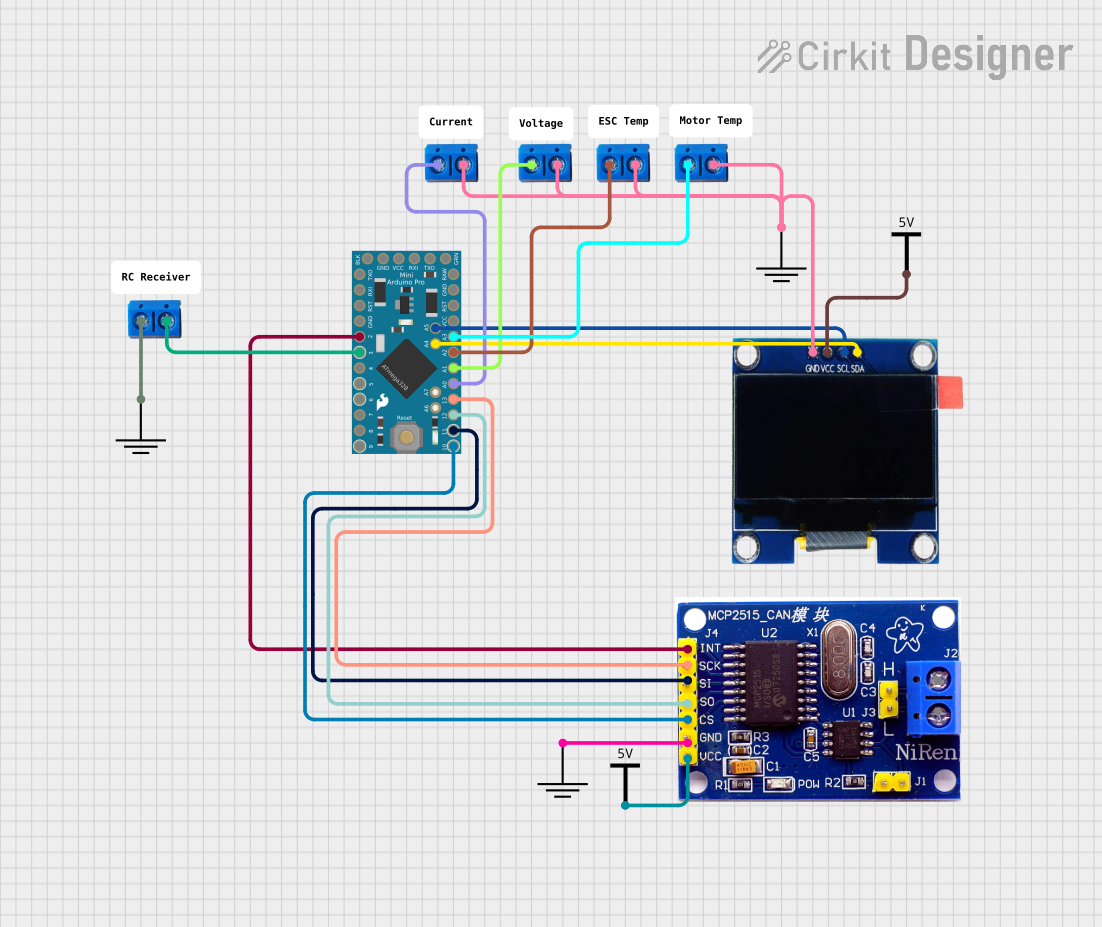
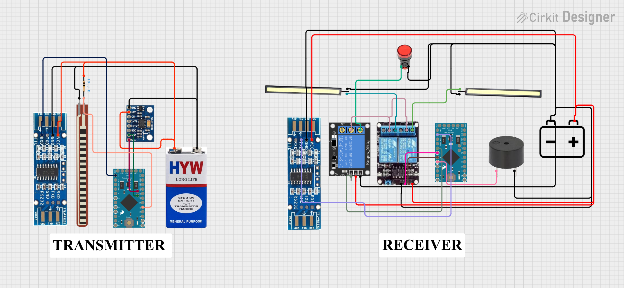
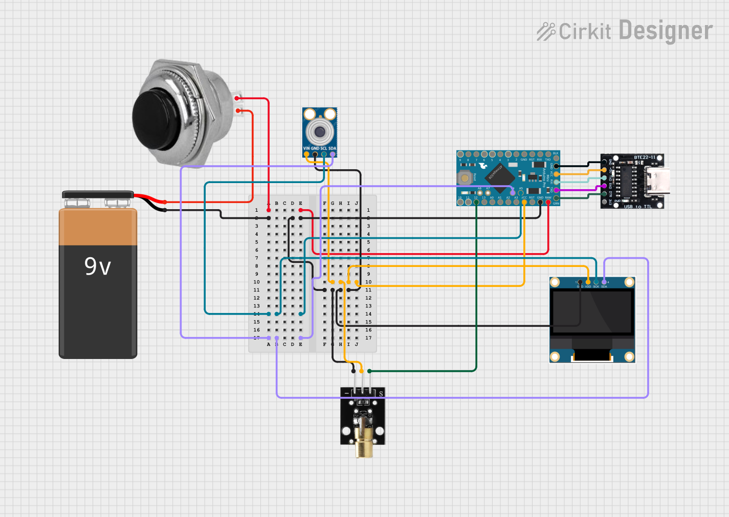
Explore Projects Built with Arduino Mega Pro Mini
Common Applications
- Robotics and automation systems
- IoT (Internet of Things) devices
- Data logging and acquisition
- Complex sensor networks
- Projects requiring multiple serial communication interfaces
Technical Specifications
Below are the key technical details of the Arduino Mega Pro Mini:
| Specification | Details |
|---|---|
| Microcontroller | ATmega2560 |
| Operating Voltage | 5V |
| Input Voltage (recommended) | 7-12V |
| Input Voltage (limit) | 6-20V |
| Digital I/O Pins | 54 (15 PWM outputs) |
| Analog Input Pins | 16 |
| Flash Memory | 256 KB (8 KB used by bootloader) |
| SRAM | 8 KB |
| EEPROM | 4 KB |
| Clock Speed | 16 MHz |
| Communication Interfaces | UART, SPI, I2C |
| Dimensions | 38 x 55 mm |
Pin Configuration and Descriptions
The Arduino Mega Pro Mini features a variety of pins for different functionalities. Below is a summary of the pin configuration:
Digital Pins
| Pin Number | Function | Description |
|---|---|---|
| 0-1 | UART (Serial) | Serial communication (RX/TX) |
| 2-13 | Digital I/O | General-purpose digital input/output pins |
| 3, 5, 6, 9-11 | PWM | Pulse Width Modulation outputs |
| 20-21 | I2C (SDA/SCL) | I2C communication pins |
Analog Pins
| Pin Number | Function | Description |
|---|---|---|
| A0-A15 | Analog Input | 16 analog input pins (10-bit resolution) |
Power Pins
| Pin Name | Function | Description |
|---|---|---|
| VIN | Input Voltage | External power input (7-12V recommended) |
| 5V | Regulated Power Out | Provides 5V regulated output |
| 3.3V | Regulated Power Out | Provides 3.3V regulated output |
| GND | Ground | Ground connection |
Usage Instructions
How to Use the Arduino Mega Pro Mini in a Circuit
Powering the Board:
- Use the VIN pin to supply an external voltage (7-12V recommended).
- Alternatively, connect the board to a computer via USB for power and programming.
Connecting I/O Devices:
- Use the digital pins for connecting LEDs, relays, or other digital devices.
- Use the analog pins for sensors that output analog signals (e.g., temperature sensors).
Programming the Board:
- Connect the board to your computer using a USB-to-serial adapter.
- Open the Arduino IDE, select "Arduino Mega 2560" as the board, and upload your code.
Serial Communication:
- Use the UART, I2C, or SPI interfaces for communication with other devices.
Important Considerations
- Ensure the input voltage does not exceed the recommended range to avoid damaging the board.
- Use appropriate resistors when connecting LEDs or other components to prevent overcurrent.
- Avoid drawing more current than the board's power pins can supply.
Example Code for Arduino Mega Pro Mini
Below is an example code to blink an LED connected to digital pin 13:
// Blink an LED connected to pin 13
// This code toggles the LED on and off every second.

void setup() {
  pinMode(13, OUTPUT); // Set pin 13 as an output
}

void loop() {
  digitalWrite(13, HIGH); // Turn the LED on
  delay(1000);            // Wait for 1 second
  digitalWrite(13, LOW);  // Turn the LED off
  delay(1000);            // Wait for 1 second
}
Troubleshooting and FAQs
Common Issues and Solutions
The board is not detected by the computer:
- Ensure the USB-to-serial adapter is properly connected.
- Install the correct drivers for the adapter.
Code upload fails:
- Verify that the correct board ("Arduino Mega 2560") is selected in the Arduino IDE.
- Check the COM port settings in the IDE.
The board does not power on:
- Confirm that the input voltage is within the recommended range.
- Check all power connections for loose wires or shorts.
Connected devices are not working:
- Double-check the wiring and ensure components are connected to the correct pins.
- Verify that the code is correctly configured for the connected devices.
FAQs
Q: Can I use the Arduino Mega Pro Mini with a battery?
A: Yes, you can power the board using a battery through the VIN pin. Ensure the battery voltage is within the recommended range (7-12V).
Q: How is the Arduino Mega Pro Mini different from the standard Arduino Mega?
A: The Mega Pro Mini offers the same functionality as the standard Arduino Mega but in a smaller form factor, making it ideal for compact projects.
Q: Can I use shields with the Arduino Mega Pro Mini?
A: While the Mega Pro Mini does not have standard shield headers, you can connect shields using jumper wires.
Q: What is the maximum current output of the 5V and 3.3V pins?
A: The 5V pin can supply up to 500mA, and the 3.3V pin can supply up to 50mA. Ensure your connected devices do not exceed these limits.