How to Use 74HC283: Examples, Pinouts, and Specs

Introduction
The 74HC283 is a high-speed CMOS device designed to perform the addition of two 4-bit binary numbers. It is a crucial component in digital electronics, particularly in arithmetic logic units (ALUs) and digital signal processing (DSP) applications. The full adder has the capability to provide a carry-in and carry-out feature, allowing for the cascading of multiple 74HC283 chips to add larger binary numbers.
Explore Projects Built with 74HC283


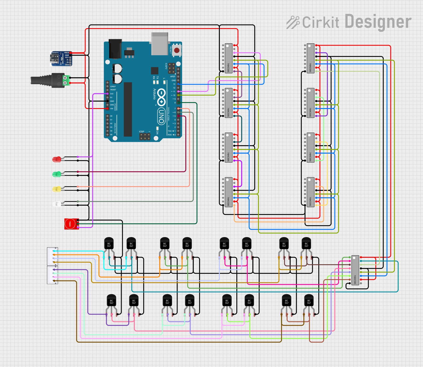
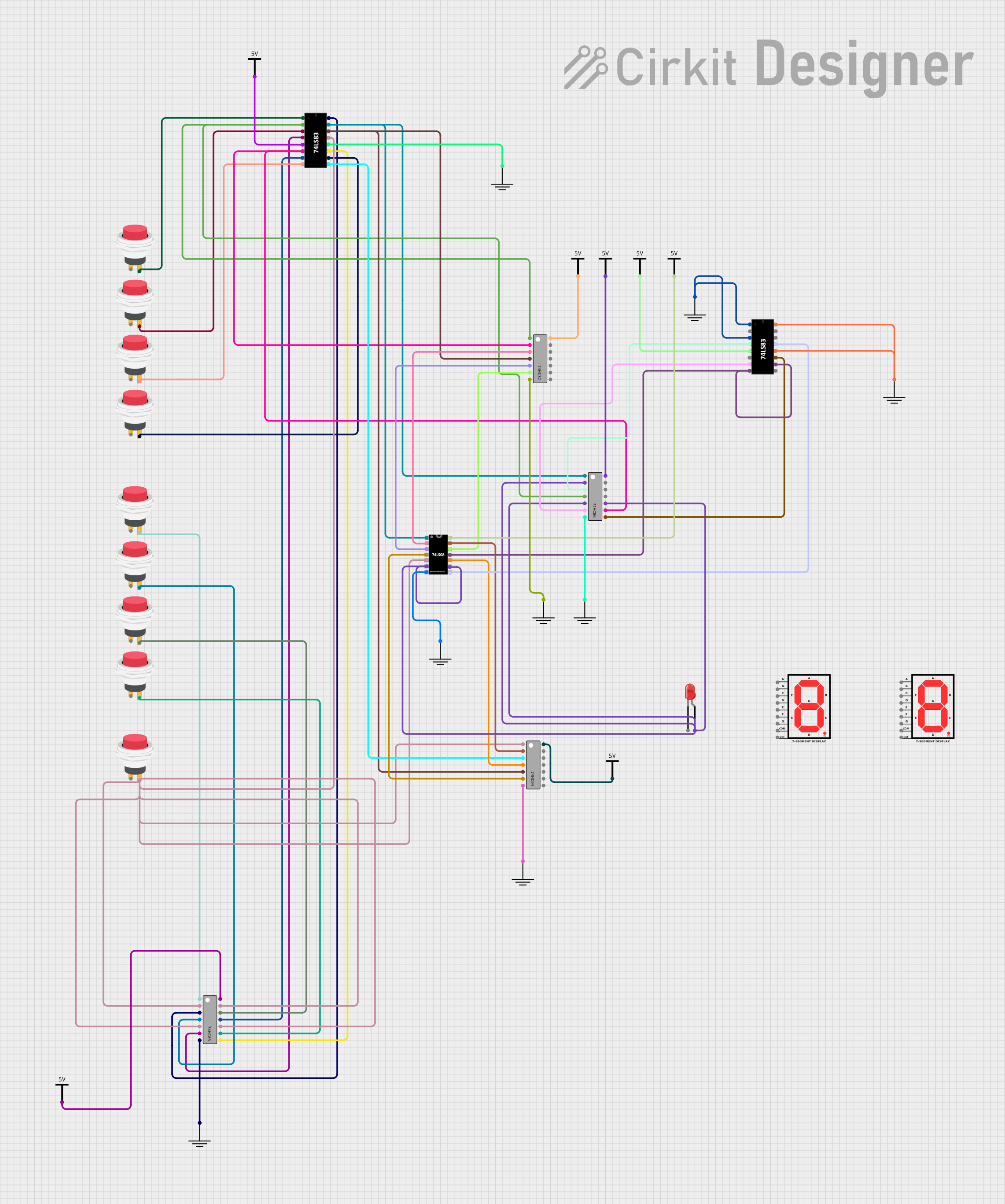
Explore Projects Built with 74HC283
Common Applications and Use Cases
- Digital calculators
- Microprocessor arithmetic units
- Complex digital systems requiring arithmetic operations
- Counters and timers
- Digital signal processing
Technical Specifications
Key Technical Details
- Supply Voltage (Vcc): 2.0V to 6.0V
- Input Voltage (Vin): -0.5V to Vcc + 0.5V
- Output Voltage (Vout): -0.5V to Vcc + 0.5V
- Operating Temperature: -40°C to +85°C
- Propagation Delay Time: Typically 8ns at Vcc = 5V, CL = 15pF
- Power Dissipation: 500 μW
Pin Configuration and Descriptions
| Pin Number | Name | Description |
|---|---|---|
| 1 | A1 | First bit of the first 4-bit binary number (LSB) |
| 2 | B1 | First bit of the second 4-bit binary number (LSB) |
| 3 | Σ1 | Sum output of the first bit (LSB) |
| 4 | GND | Ground (0V) |
| 5 | Σ2 | Sum output of the second bit |
| 6 | B2 | Second bit of the second 4-bit binary number |
| 7 | A2 | Second bit of the first 4-bit binary number |
| 8 | C0 | Carry input (LSB) |
| 9 | A3 | Third bit of the first 4-bit binary number |
| 10 | B3 | Third bit of the second 4-bit binary number |
| 11 | Σ3 | Sum output of the third bit |
| 12 | C3 | Carry output of the third bit |
| 13 | Σ4 | Sum output of the fourth bit (MSB) |
| 14 | B4 | Fourth bit of the second 4-bit binary number (MSB) |
| 15 | A4 | Fourth bit of the first 4-bit binary number (MSB) |
| 16 | Vcc | Positive supply voltage |
Usage Instructions
How to Use the Component in a Circuit
- Connect Vcc to a +5V power supply and GND to the ground of the circuit.
- Apply the two 4-bit binary numbers to the A and B inputs (A1-A4 and B1-B4).
- Connect the C0 pin to a low logic level if there is no carry-in; otherwise, connect it to the carry-out of the preceding adder.
- The sum outputs (Σ1-Σ4) will provide the result of the addition.
- The C3 pin will output the carry-out, which can be connected to the carry-in (C0) of another 74HC283 chip if cascading is required.
Important Considerations and Best Practices
- Ensure that the power supply voltage (Vcc) is within the specified range.
- Avoid applying voltages to the inputs that exceed the supply voltage (Vcc).
- Decoupling capacitors (typically 0.1 μF) should be placed close to the Vcc pin to filter out noise.
- When cascading multiple 74HC283 chips, ensure that the carry-out of one chip is correctly connected to the carry-in of the next chip.
Troubleshooting and FAQs
Common Issues Users Might Face
- Incorrect Sum Output: Verify that all input pins are receiving the correct logic levels and that there is no floating input.
- No Carry-Out Signal: Check the connections of the carry-out and carry-in pins when cascading multiple chips.
Solutions and Tips for Troubleshooting
- Double-check the wiring against the pin configuration table.
- Use a multimeter to ensure that the Vcc and GND are correctly supplied.
- Test each input pin with known logic levels to confirm that the chip is functioning correctly.
FAQs
Q: Can the 74HC283 adder handle decimal numbers? A: The 74HC283 is a binary adder and operates with binary numbers. To handle decimal numbers, a binary-coded decimal (BCD) system must be used.
Q: How can I add numbers larger than 4 bits? A: To add numbers larger than 4 bits, you can cascade multiple 74HC283 chips. Connect the carry-out (C3) of one chip to the carry-in (C0) of the next chip in the series.
Q: What is the maximum number of 74HC283 chips that can be cascaded? A: There is no strict maximum, but propagation delay accumulates with each added chip, which can limit the speed of the overall operation.
Example Code for Arduino UNO
The following example demonstrates how to use the 74HC283 with an Arduino UNO to perform a simple addition.
// Define the pins connected to the 74HC283
const int A[] = {2, 3, 4, 5}; // A1-A4 connected to digital pins 2-5
const int B[] = {6, 7, 8, 9}; // B1-B4 connected to digital pins 6-9
const int SUM[] = {10, 11, 12, 13}; // Σ1-Σ4 connected to digital pins 10-13
const int CARRY_IN = A0; // C0 connected to analog pin A0
const int CARRY_OUT = A1; // C3 connected to analog pin A1

void setup() {
  // Initialize all the A and B pins as outputs
  for (int i = 0; i < 4; i++) {
    pinMode(A[i], OUTPUT);
    pinMode(B[i], OUTPUT);
  }
  // Initialize SUM pins as inputs
  for (int i = 0; i < 4; i++) {
    pinMode(SUM[i], INPUT);
  }
  // Initialize carry in and carry out pins
  pinMode(CARRY_IN, OUTPUT);
  pinMode(CARRY_OUT, INPUT);

  // Start the serial communication
  Serial.begin(9600);
}

void loop() {
  // Example addition of two 4-bit numbers: 1010 (A) + 0111 (B)
  digitalWrite(A[0], HIGH);
  digitalWrite(A[1], LOW);
  digitalWrite(A[2], HIGH);
  digitalWrite(A[3], LOW);

  digitalWrite(B[0], LOW);
  digitalWrite(B[1], HIGH);
  digitalWrite(B[2], HIGH);
  digitalWrite(B[3], HIGH);

  // No carry-in for this example
  digitalWrite(CARRY_IN, LOW);

  // Read the sum and carry out
  int sum = 0;
  for (int i = 0; i < 4; i++) {
    sum |= digitalRead(SUM[i]) << i;
  }
  int carryOut = digitalRead(CARRY_OUT);

  // Print the result
  Serial.print("Sum: ");
  Serial.println(sum, BIN);
  Serial.print("Carry Out: ");
  Serial.println(carryOut);

  // Small delay before the next calculation
  delay(1000);
}
This code sets up the Arduino to communicate with the 74HC283 and perform a simple addition of two binary numbers. The results are printed to the serial monitor in binary format.