How to Use MAGNETIC CONTACTOR: Examples, Pinouts, and Specs
Introduction
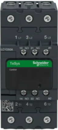
The Schneider LC1D50AM7 Magnetic Contactor is an electrically controlled switch designed for high-current applications. It operates using an electromagnet to control the switching mechanism, making it ideal for managing power circuits. Unlike standard relays, magnetic contactors are specifically engineered to handle higher loads, ensuring reliable performance in demanding environments.
Explore Projects Built with MAGNETIC CONTACTOR


Explore Projects Built with MAGNETIC CONTACTOR
Common Applications and Use Cases
- Motor control in industrial automation systems
- Switching and controlling lighting circuits
- HVAC systems for compressor and fan control
- Power distribution and load management
- Protection and isolation of electrical equipment
Technical Specifications
Key Technical Details
| Parameter | Value |
|---|---|
| Manufacturer | Schneider |
| Part Number | LC1D50AM7 |
| Rated Operational Voltage | 690V AC |
| Rated Current (AC-3) | 50A |
| Coil Voltage | 220V AC (50/60 Hz) |
| Number of Poles | 3P (Three Poles) |
| Auxiliary Contacts | 1 NO + 1 NC |
| Mechanical Durability | 10 million operations |
| Electrical Durability | 1 million operations (AC-3) |
| Operating Temperature Range | -5°C to +60°C |
| Mounting Type | DIN Rail or Panel Mount |
| Dimensions (H x W x D) | 120 x 85 x 120 mm |
| Weight | 1.2 kg |
Pin Configuration and Descriptions
The LC1D50AM7 has terminals for both power and control connections. Below is the pin configuration:
Power Terminals
| Terminal Label | Description |
|---|---|
| L1, L2, L3 | Input terminals for three-phase AC |
| T1, T2, T3 | Output terminals to the load |
Control Terminals
| Terminal Label | Description |
|---|---|
| A1, A2 | Coil terminals for control voltage |
Auxiliary Contacts
| Terminal Label | Description |
|---|---|
| 13-14 | Normally Open (NO) auxiliary contact |
| 21-22 | Normally Closed (NC) auxiliary contact |
Usage Instructions
How to Use the Component in a Circuit
Power Connections:
- Connect the three-phase AC supply to the input terminals (L1, L2, L3).
- Connect the load (e.g., motor) to the output terminals (T1, T2, T3).
Control Circuit:
- Supply the control voltage (220V AC) to the coil terminals (A1, A2).
- Use a push-button or switch in series with the coil to control the contactor.
Auxiliary Contacts:
- Use the auxiliary contacts (13-14 and 21-22) for signaling or interlocking purposes.
Mounting:
- Secure the contactor on a DIN rail or directly onto a panel using screws.
Important Considerations and Best Practices
- Ensure the coil voltage matches the rated control voltage (220V AC).
- Use proper cable sizing to handle the rated current (50A) without overheating.
- Install surge suppressors across the coil terminals to protect against voltage spikes.
- Verify the contactor's compatibility with the load type (e.g., motor, resistive load).
- Regularly inspect the contactor for wear and tear, especially in high-duty applications.
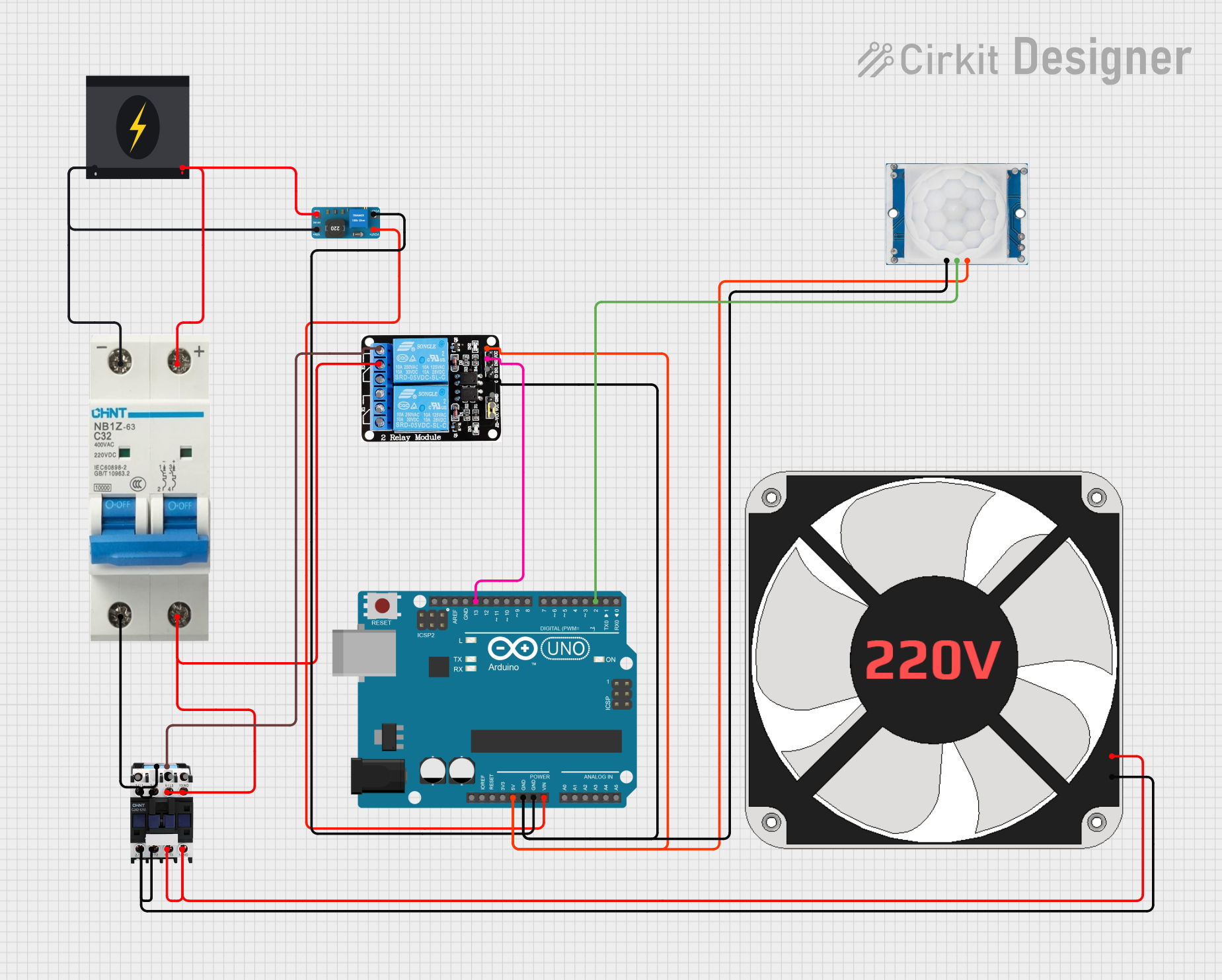
Example: Connecting to an Arduino UNO
While magnetic contactors are not directly controlled by microcontrollers like the Arduino UNO due to their high voltage and current requirements, you can use a relay module to interface the Arduino with the contactor. Below is an example:
Circuit Description
- The Arduino controls a relay module.
- The relay module switches the contactor's coil (A1, A2) using a 220V AC supply.
Arduino Code
// Magnetic Contactor Control using Arduino and Relay Module
// Pin 7 is used to control the relay module

const int relayPin = 7; // Define the relay control pin

void setup() {
  pinMode(relayPin, OUTPUT); // Set relay pin as output
  digitalWrite(relayPin, LOW); // Ensure relay is off at startup
}

void loop() {
  // Turn on the contactor
  digitalWrite(relayPin, HIGH); // Activate relay
  delay(5000); // Keep contactor on for 5 seconds

  // Turn off the contactor
  digitalWrite(relayPin, LOW); // Deactivate relay
  delay(5000); // Wait for 5 seconds before repeating
}
Notes:
- Use a relay module rated for 220V AC to control the contactor's coil.
- Ensure proper isolation between the Arduino and the high-voltage circuit.
Troubleshooting and FAQs
Common Issues and Solutions
Contactor Does Not Energize:
- Cause: No control voltage at the coil terminals (A1, A2).
- Solution: Check the control circuit and ensure the correct voltage is supplied.
Excessive Heating:
- Cause: Overloaded power terminals or loose connections.
- Solution: Verify the load current and tighten all connections.
Chattering Noise:
- Cause: Insufficient or unstable control voltage.
- Solution: Check the control voltage source and ensure it is stable.
Auxiliary Contacts Not Working:
- Cause: Miswiring or damaged contacts.
- Solution: Verify the wiring and inspect the auxiliary contacts for wear.
FAQs
Q1: Can the LC1D50AM7 be used for single-phase loads?
A1: Yes, but only two poles (e.g., L1 and L2) should be used for single-phase applications.
Q2: How do I know if the contactor is energized?
A2: You will hear a clicking sound, and the auxiliary NO contact (13-14) will close.
Q3: Can I use a DC control voltage for the coil?
A3: No, the LC1D50AM7 is designed for 220V AC control voltage only.
Q4: What is the purpose of the auxiliary contacts?
A4: Auxiliary contacts are used for signaling, interlocking, or controlling other devices in the circuit.
Q5: How often should the contactor be maintained?
A5: Inspect the contactor every 6-12 months, depending on the operating conditions and duty cycle.