How to Use ICS-43434: Examples, Pinouts, and Specs
Introduction
The ICS-43434 is a high-performance, low-power digital MEMS (Micro-Electro-Mechanical Systems) microphone manufactured by TDK InvenSense. It is designed for audio applications requiring high-quality sound capture in a compact form factor. The ICS-43434 features a high signal-to-noise ratio (SNR) and low power consumption, making it ideal for use in smartphones, tablets, laptops, and other portable devices. Its digital I²S (Inter-IC Sound) output eliminates the need for an external analog-to-digital converter, simplifying integration into digital audio systems.
Explore Projects Built with ICS-43434


Explore Projects Built with ICS-43434
Common Applications
- Smartphones and tablets
- Wearable devices
- Smart home devices (e.g., smart speakers, voice assistants)
- Audio recording equipment
- IoT devices with voice recognition capabilities
Technical Specifications
The ICS-43434 is designed to deliver high-quality audio performance while maintaining low power consumption. Below are its key technical specifications:
| Parameter | Value |
|---|---|
| Supply Voltage (VDD) | 1.62V to 3.63V |
| Signal-to-Noise Ratio (SNR) | 65 dB |
| Acoustic Overload Point (AOP) | 120 dB SPL |
| Frequency Response | 50 Hz to 20 kHz |
| Power Consumption | 650 µA (typical) |
| Output Format | I²S (Inter-IC Sound) |
| Sensitivity | -26 dBFS ±1 dB |
| Operating Temperature Range | -40°C to +85°C |
| Package Dimensions | 3.50 mm × 2.65 mm × 0.98 mm |
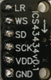
Pin Configuration and Descriptions
The ICS-43434 has a 5-pin configuration. The table below describes each pin:
| Pin Name | Pin Number | Description |
|---|---|---|
| VDD | 1 | Power supply input (1.62V to 3.63V). Connect to a stable power source. |
| GND | 2 | Ground. Connect to the system ground. |
| WS | 3 | Word Select (I²S frame synchronization). Determines left or right channel. |
| SCK | 4 | Serial Clock (I²S clock input). Provides the clock signal for data transfer. |
| SD | 5 | Serial Data (I²S data output). Outputs the digital audio signal. |
Usage Instructions
How to Use the ICS-43434 in a Circuit
- Power Supply: Connect the VDD pin to a stable power source within the range of 1.62V to 3.63V. Connect the GND pin to the system ground.
- I²S Interface: Connect the WS, SCK, and SD pins to the corresponding I²S interface pins on your microcontroller or audio processor.
- WS: Connect to the Word Select pin of the I²S interface.
- SCK: Connect to the Serial Clock pin of the I²S interface.
- SD: Connect to the Serial Data input pin of the I²S interface.
- Bypass Capacitor: Place a 0.1 µF ceramic capacitor close to the VDD pin to filter out power supply noise.
- PCB Layout: Ensure proper grounding and minimize noise by using a ground plane and keeping traces short and direct.
Important Considerations
- The ICS-43434 outputs digital audio data in I²S format. Ensure your microcontroller or audio processor supports I²S.
- The microphone is omnidirectional, meaning it captures sound from all directions. Position it appropriately for your application.
- Avoid exposing the microphone to excessive moisture, dust, or mechanical stress during assembly.
Example: Connecting ICS-43434 to an Arduino UNO
The Arduino UNO does not natively support I²S. To use the ICS-43434 with an Arduino, you will need an external I²S interface module or a microcontroller with built-in I²S support (e.g., ESP32). Below is an example code snippet for an ESP32:
#include <driver/i2s.h>

// I²S configuration for the ICS-43434
#define I2S_WS_PIN  25  // Word Select pin
#define I2S_SCK_PIN 26  // Serial Clock pin
#define I2S_SD_PIN  22  // Serial Data pin

void setup() {
  // Configure I²S driver
  i2s_config_t i2s_config = {
    .mode = (i2s_mode_t)(I2S_MODE_MASTER | I2S_MODE_RX), // Master mode, receive data
    .sample_rate = 16000,                               // Sampling rate: 16 kHz
    .bits_per_sample = I2S_BITS_PER_SAMPLE_32BIT,       // 32-bit data
    .channel_format = I2S_CHANNEL_FMT_ONLY_LEFT,        // Single channel (left)
    .communication_format = I2S_COMM_FORMAT_I2S,       // I²S format
    .intr_alloc_flags = 0,                              // Default interrupt allocation
    .dma_buf_count = 8,                                 // Number of DMA buffers
    .dma_buf_len = 64                                   // Length of each DMA buffer
  };

  // Configure I²S pins
  i2s_pin_config_t pin_config = {
    .bck_io_num = I2S_SCK_PIN,  // Serial Clock pin
    .ws_io_num = I2S_WS_PIN,    // Word Select pin
    .data_out_num = I2S_PIN_NO_CHANGE, // No data output
    .data_in_num = I2S_SD_PIN   // Serial Data pin
  };

  // Install and start the I²S driver
  i2s_driver_install(I2S_NUM_0, &i2s_config, 0, NULL);
  i2s_set_pin(I2S_NUM_0, &pin_config);
}

void loop() {
  // Buffer to store audio data
  uint8_t audio_data[128];
  size_t bytes_read;

  // Read audio data from the ICS-43434
  i2s_read(I2S_NUM_0, audio_data, sizeof(audio_data), &bytes_read, portMAX_DELAY);

  // Process the audio data (e.g., send it to a server or save it to storage)
}
Troubleshooting and FAQs
Common Issues
No Audio Output
- Ensure the ICS-43434 is powered correctly (VDD and GND connections).
- Verify that the I²S pins (WS, SCK, SD) are connected to the correct pins on the microcontroller.
- Check the I²S configuration in your microcontroller's code (e.g., sample rate, bit depth).
Distorted Audio
- Ensure the microphone is not exposed to sound levels exceeding its Acoustic Overload Point (120 dB SPL).
- Verify that the I²S clock frequency matches the microphone's requirements.
Excessive Noise
- Place a 0.1 µF bypass capacitor close to the VDD pin to filter power supply noise.
- Minimize electromagnetic interference by keeping traces short and using a ground plane.
FAQs
Q: Can the ICS-43434 be used with a Raspberry Pi?
A: Yes, the ICS-43434 can be connected to the I²S interface of a Raspberry Pi. Ensure the Raspberry Pi's I²S pins are configured correctly in the software.
Q: What is the maximum distance between the ICS-43434 and the microcontroller?
A: To minimize signal degradation, keep the distance as short as possible. Long traces may require additional shielding or buffering.
Q: Does the ICS-43434 require an external ADC?
A: No, the ICS-43434 has a built-in ADC and outputs digital audio data in I²S format.