How to Use SSD1331 7-pin 0.95" OLED: Examples, Pinouts, and Specs
Introduction
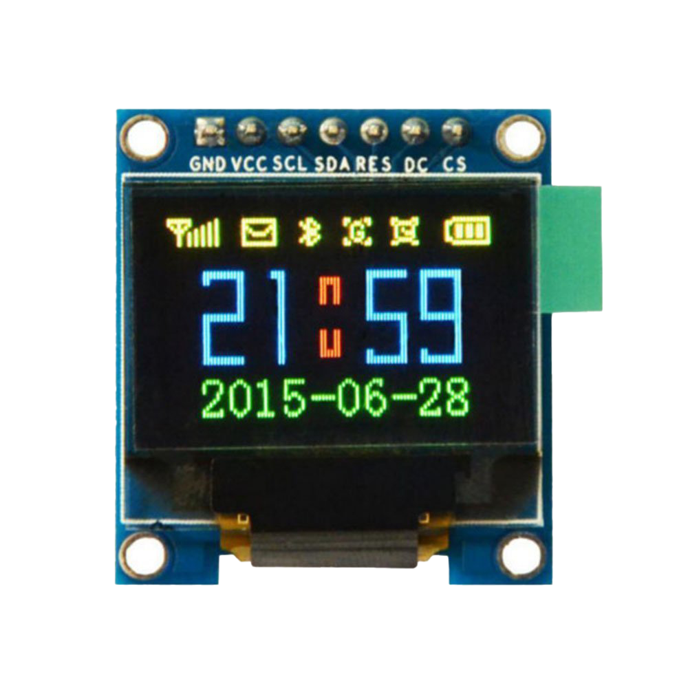
The SSD1331 7-pin 0.95" OLED is a compact, high-resolution display module manufactured by HiLetGo. It features the SSD1331 driver IC, which enables vibrant 16-bit color rendering and smooth graphics performance. With its 0.95-inch diagonal size, this OLED display is ideal for applications requiring a small yet visually striking interface. The module's 7-pin interface simplifies integration with microcontrollers, making it a popular choice for hobbyists and professionals alike.
Explore Projects Built with SSD1331 7-pin 0.95" OLED


Explore Projects Built with SSD1331 7-pin 0.95" OLED
Common Applications and Use Cases
- Wearable devices and smart gadgets
- Portable instrumentation displays
- IoT dashboards and status indicators
- Embedded systems requiring graphical output
- Educational and prototyping projects
Technical Specifications
The following table outlines the key technical details of the SSD1331 7-pin 0.95" OLED module:
| Parameter | Specification |
|---|---|
| Manufacturer | HiLetGo |
| Part ID | SSD1331 |
| Display Type | OLED (Organic Light Emitting Diode) |
| Screen Size | 0.95 inches |
| Resolution | 96 x 64 pixels |
| Color Depth | 16-bit (65,536 colors) |
| Driver IC | SSD1331 |
| Interface Type | SPI (Serial Peripheral Interface) |
| Operating Voltage | 3.3V to 5V |
| Operating Current | ~20mA (typical) |
| Viewing Angle | >160° |
| Operating Temperature | -40°C to +70°C |
Pin Configuration and Descriptions
The SSD1331 module features a 7-pin interface. Below is the pinout and description:
| Pin | Name | Description |
|---|---|---|
| 1 | GND | Ground connection |
| 2 | VCC | Power supply (3.3V or 5V) |
| 3 | SCL | Serial Clock Line (SPI clock input) |
| 4 | SDA | Serial Data Line (SPI data input) |
| 5 | RES | Reset pin (active low, used to reset the display) |
| 6 | DC | Data/Command control pin (high for data, low for command) |
| 7 | CS | Chip Select (active low, used to enable communication with the display module) |
Usage Instructions
How to Use the SSD1331 in a Circuit
- Power Supply: Connect the
VCCpin to a 3.3V or 5V power source and theGNDpin to ground. - SPI Communication: Connect the
SCL(clock) andSDA(data) pins to the corresponding SPI pins on your microcontroller. - Control Pins:
- Connect the
RESpin to a GPIO pin on your microcontroller for resetting the display. - Use the
DCpin to toggle between data and command modes. - Connect the
CSpin to a GPIO pin to enable or disable communication with the display.
- Connect the
- Pull-up Resistors: Ensure proper pull-up resistors are used if required by your microcontroller's SPI configuration.
Example Code for Arduino UNO
Below is an example of how to interface the SSD1331 OLED with an Arduino UNO using the Adafruit SSD1331 library:
#include <Adafruit_GFX.h>       // Core graphics library
#include <Adafruit_SSD1331.h>   // SSD1331 OLED driver library
#include <SPI.h>                // SPI library

// Pin definitions for the SSD1331 OLED
#define sclk 13  // SPI clock pin
#define mosi 11  // SPI data pin
#define cs   10  // Chip select pin
#define rst   9  // Reset pin
#define dc    8  // Data/Command pin

// Initialize the SSD1331 display
Adafruit_SSD1331 display = Adafruit_SSD1331(cs, dc, rst);

void setup() {
  // Initialize the display
  display.begin();

  // Clear the screen with a black background
  display.fillScreen(0x0000);

  // Display a message
  display.setTextColor(0xFFFF); // White text
  display.setCursor(0, 0);      // Set cursor to top-left corner
  display.println("Hello, SSD1331!");
}

void loop() {
  // Add your code here to update the display
}
Important Considerations and Best Practices
- Voltage Compatibility: Ensure the module's
VCCpin matches your microcontroller's voltage level (3.3V or 5V). - Reset Pin: Always connect the
RESpin to a GPIO pin to allow proper initialization of the display. - SPI Speed: Use an appropriate SPI clock speed (e.g., 8 MHz) to ensure reliable communication.
- Library Support: Use a compatible library like Adafruit SSD1331 to simplify development and access advanced features.
Troubleshooting and FAQs
Common Issues and Solutions
Display Not Turning On:
- Verify the power supply connections (
VCCandGND). - Check if the
RESpin is properly connected and initialized in your code.
- Verify the power supply connections (
No Output or Garbled Display:
- Ensure the SPI connections (
SCL,SDA,CS,DC) are correct. - Verify that the SPI clock speed is within the module's supported range.
- Ensure the SPI connections (
Flickering or Artifacts:
- Check for loose connections or poor soldering on the pins.
- Reduce the SPI clock speed to improve stability.
Library Errors:
- Ensure the Adafruit SSD1331 library is installed and up to date.
- Verify that the pin definitions in your code match your hardware setup.
FAQs
Q: Can I use the SSD1331 with a 3.3V microcontroller?
A: Yes, the SSD1331 module supports both 3.3V and 5V logic levels, making it compatible with a wide range of microcontrollers.
Q: What is the maximum SPI clock speed supported by the SSD1331?
A: The SSD1331 typically supports SPI clock speeds up to 10 MHz. However, for reliable operation, 8 MHz is recommended.
Q: Can I use the SSD1331 for video playback?
A: While the SSD1331 can display images and animations, its resolution and refresh rate are not suitable for high-quality video playback.
Q: Is the display sunlight-readable?
A: The OLED display offers good brightness and contrast but may not be fully readable under direct sunlight.
By following this documentation, you can effectively integrate the SSD1331 7-pin 0.95" OLED into your projects and troubleshoot common issues with ease.